Asus VIA User Manual - Page 34
Pin Primary Ata100/secondary Ata100
 |
View all Asus VIA manuals
Add to My Manuals
Save this manual to your list of manuals |
Page 34 highlights
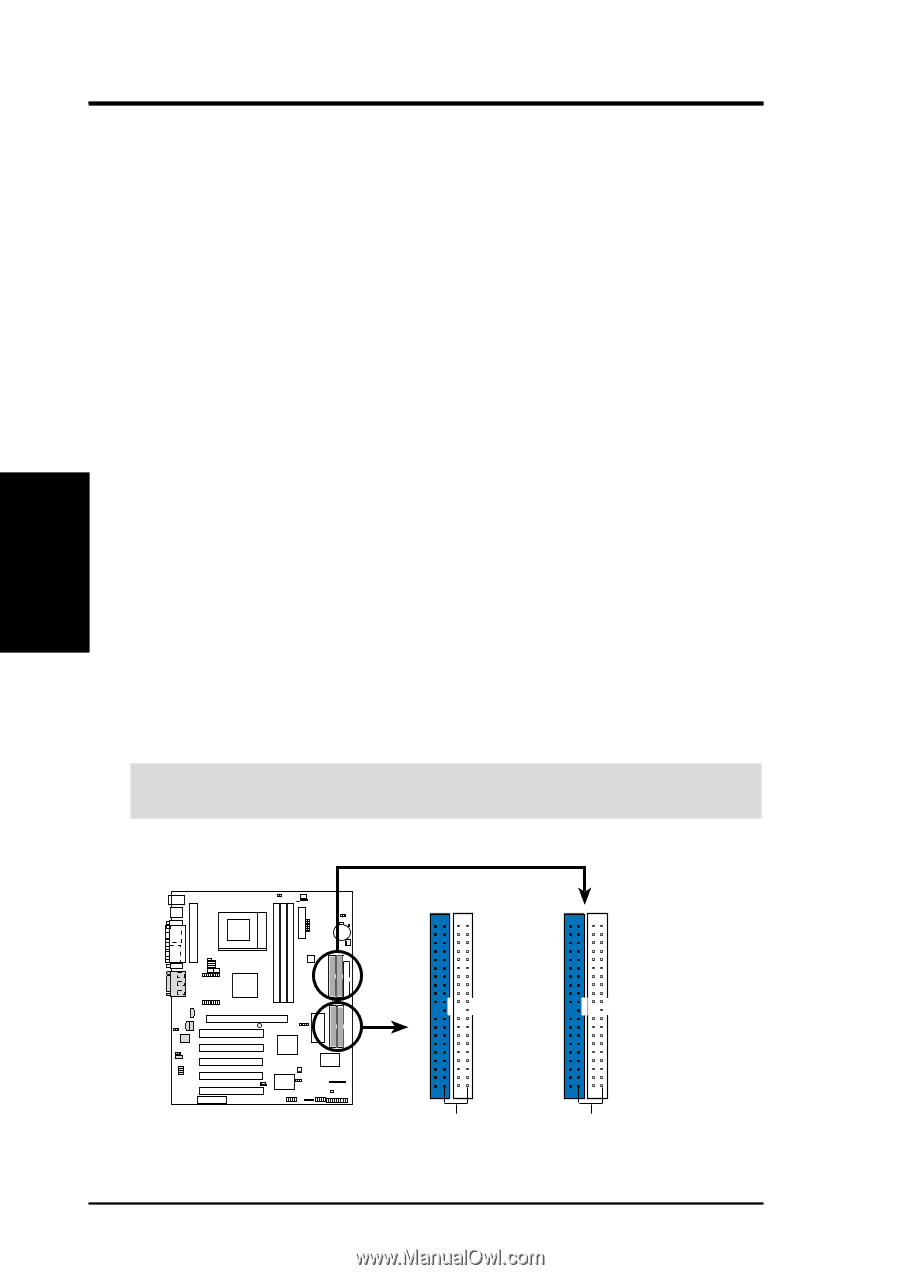
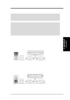
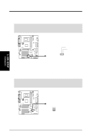
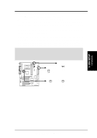
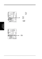
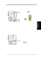
3. HARDWARE SETUP 9) Primary (Blue) / Secondary IDE Connectors (40-1 pin PRIMARY IDE/SECONDARY IDE) (40-1 pin PRIMARY ATA100/SECONDARY ATA100) These connectors support the provided IDE hard disk ribbon cables. Connect the cable's blue connector to the motherboard's primary (recommended) or secondary IDE connector, and then connect the corresponding gray connector to your UltraDMA/100 / UltraDMA/66 slave device (hard disk drive) and the black connector to your UltraDMA/100 / UltraDMA/66 master device. It is recommended that non-UltraDMA/100 / Ultra/66 devices be connected to the secondary IDE connector. NOTE: UltraDMA/100 is backward compatible with DMA/66, DMA/33, and DMA and with existing DMA devices and systems so there is no need to upgrade current EIDE/IDE drives and host systems. If you install two hard disks, you must configure the second drive to Slave mode by setting its jumper accordingly. Refer to your hard disk documentation for the jumper settings. BIOS now supports specific device bootup (see 4.6 Boot Menu). (Pin 20 is removed to prevent inserting in the wrong orientation when using ribbon cables with pin 20 plugged). If you have more than two UltraDMA/100 / UltraDMA/66 devices, you will need to purchase another UltraDMA/100 / UltraDMA/66 cable. NOTE: The hole near the blue connector on the UltraDMA/100 / UltraDMA/66 cable is intentional. TIP: You may configure two hard disks to be both Masters with two ribbon cables - one for the primary IDE connector and another for the secondary IDE connector. You may install one operating system on an IDE drive and another on a SCSI drive and select the boot disk through 4.6 Boot Menu. IMPORTANT: UltraDMA/66 and UltraDMA/100 IDE devices require a 40-pin 80-conductor cable to be enabled. NOTE: Orient the red markings (usually zigzag) on the IDE ribbon cable to PIN 1. 3. H/W SETUP Connectors Primary Ultra ATA100 IDE Connector Secondary Ultra ATA100 IDE Connector Primary IDE Connector Secondary IDE Connector 01 01 01 A7V A7V IDE Connectors PIN 1 PIN 1 34 ASUS A7V User's Manual
-
 1
1 -
2
-
3
-
4
-
5
-
6
-
7
-
8
-
9
-
10
-
11
-
12
-
13
-
14
-
15
-
16
-
17
-
18
-
19
-
20
-
21
-
22
-
23
-
24
-
25
-
26
-
27
-
28
-
 29
29 -
 30
30 -
 31
31 -
 32
32 -
 33
33 -
 34
34 -
 35
35 -
 36
36 -
 37
37 -
 38
38 -
 39
39 -
40
-
41
-
42
-
43
-
44
-
45
-
46
-
47
-
48
-
49
-
50
-
51
-
52
-
53
-
54
-
55
-
56
-
57
-
58
-
59
-
60
-
61
-
62
-
63
-
64
-
65
-
66
-
67
-
68
-
69
-
70
-
71
-
72
-
73
-
74
-
75
-
76
-
77
-
78
-
79
-
80
-
81
-
82
-
83
-
84
-
85
-
86
-
87
-
88
-
89
-
90
-
91
-
92
-
93
-
94
-
95
-
96
-
97
-
98
-
99
-
100
 |
 |