Asus VIA User Manual - Page 16
ASUS A7V User's Manual
 |
View all Asus VIA manuals
Add to My Manuals
Save this manual to your list of manuals |
Page 16 highlights
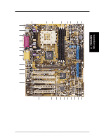
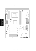
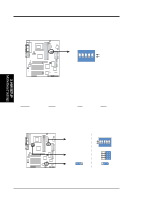
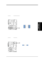
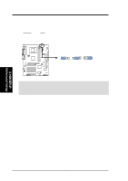
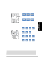
3. HARDWARE SETUP 16) MIC2 17) USB3A, USBPORT, USB3 18) SMB 19) ATXPWR 20) JTPWR 21) IDELED 22) PWR.LED (PANEL) 23) SPEAKER (PANEL) 24) MSG.LED (PANEL) 25) SMI (PANEL) 26) PWR.SW (PANEL) 27) RESET (PANEL) p. 38 Internal Microphone Header (3 pins) (optional) p. 39 USB Headers (5-1 pins / 10-1 pins) p. 39 SMBus Connector (5-1 pins) p. 40 ATX Power Supply Connector (20 pins) p. 40 Power Supply Thermal Sensor Connector (2 pins) p. 41 IDE Activity LED (2 pins) p. 42 System Power LED Lead (3 pins) p. 42 System Warning Speaker Connector (4 pins) p. 42 System Message LED (2 pins) p. 42 System Management Interrupt Lead (2 pins) p. 42 ATX / Soft-Off Switch Lead (2 pins) p. 42 Reset Switch Lead (2 pins) 3. H/W SETUP Layout Contents 16 ASUS A7V User's Manual
-
 1
1 -
2
-
3
-
4
-
5
-
6
-
7
-
8
-
9
-
10
-
 11
11 -
 12
12 -
 13
13 -
 14
14 -
 15
15 -
 16
16 -
 17
17 -
 18
18 -
 19
19 -
 20
20 -
 21
21 -
22
-
23
-
24
-
25
-
26
-
27
-
28
-
29
-
30
-
31
-
32
-
33
-
34
-
35
-
36
-
37
-
38
-
39
-
40
-
41
-
42
-
43
-
44
-
45
-
46
-
47
-
48
-
49
-
50
-
51
-
52
-
53
-
54
-
55
-
56
-
57
-
58
-
59
-
60
-
61
-
62
-
63
-
64
-
65
-
66
-
67
-
68
-
69
-
70
-
71
-
72
-
73
-
74
-
75
-
76
-
77
-
78
-
79
-
80
-
81
-
82
-
83
-
84
-
85
-
86
-
87
-
88
-
89
-
90
-
91
-
92
-
93
-
94
-
95
-
96
-
97
-
98
-
99
-
100
 |
 |
