Brother International EF4-B561 Service Manual - Page 11
Description, Mechanism
 |
View all Brother International EF4-B561 manuals
Add to My Manuals
Save this manual to your list of manuals |
Page 11 highlights
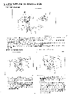
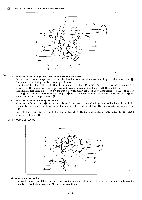
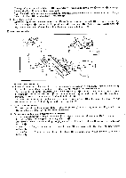
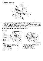
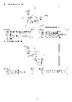
a DESCRIPTION OF MECHANISM M NEEDLE BAR MECHANISM „ca -53 CD • In case that crank shaft 0 may rotate to the direction indicated with arrow, with needle bar and upper knife eccentric cam (9, needle arm driving crank rod 41) connected with crank shaft moves up and down. • As the upper portion of needle arm driving crank rod 0 is connected with needle arm driving lever 0 with its pin 0, needle bar crank shaft 0 gets the oscillating movement. • Needle bar clamp Q connected needle bar crank shaft 0 with needle bar crank shaft 0 and needle bar link is fitted into the top of needle bar crank shaft and gets up and down movement. m • Needle bar rji that is held by needle bar clamp Q is guided by needle bar bushing lower ® upper and needle bar bushing 2 UNDER LOOPER MECHANISM El OVER LOOPER MECHANISM 0 • In case that crank shaft 0 may rotate to the direction indicated with arrow, with under looper eccentric cam 0, under looper connecting rod moves up and down. • Under looper 0 fitted into under looper holder 0 gets the oscillating movement with the intermediate action of under looper connecting lever 0 connected with under looper connecting rod €) and under looper lever shaft 0. - 9- • In case that crank shaft 0 may rotate to the direc- tion indicated with arrow, with over looper eccentric cam 40, over looper connecting rod ID moves up and down. • Over looper driving lever Q gets the oscillating move- o ment with the intermediate action of over looper connecting lever connected with over looper con- necting rod ID and over looper lever shaft 10 Its oscillation motion makes the over looper 41) describe an ideal orbit about over looper holder and over looper holder guide assembly 4Th via over looper holder pin 0. 0
-
 1
1 -
2
-
3
-
4
-
5
-
 6
6 -
 7
7 -
 8
8 -
 9
9 -
 10
10 -
 11
11 -
 12
12 -
 13
13 -
 14
14 -
 15
15 -
 16
16 -
17
-
18
-
19
-
20
-
21
-
22
-
23
-
24
-
25
-
26
-
27
-
28
-
29
-
30
-
31
-
32
-
33
-
34
-
35
-
36
-
37
-
38
-
39
 |
 |
