Brother International EF4-B561 Service Manual - Page 18
Assembling, Adjustment, Procedures
 |
View all Brother International EF4-B561 manuals
Add to My Manuals
Save this manual to your list of manuals |
Page 18 highlights
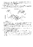
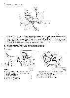
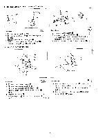
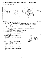
5. ASSEMBLING ADJUSTMENT PROCEDURES ❑i NEEDLE BAR MECHANISM 5 C9.) (B571) -® 0 Procedures Q'ty of screw 1 Insert needle bar 0 into needle bar clamp 0. 2 Turn the pulley until the needle bar clamp 41) is raised to the highest position, and then temporarily fasten the needle bar 0 at a height where the needle clamp ID is barely hidden in needle bar bushing 1 lower 0. 3 Install face plate 41) to the machine body. 4 (Install stopper spring at the same time, and adjust it when face plate cover 0 is closed without 3 (13581) cranky.) 4 Install needle mechanism cover Q to the machine body firmly putting of face plate (1) lightly, then 7 take care not make any clearance. 5 Install needle thread take-up supporter 0 to needle bar clamp O. 1 6 Install needle thread guide (A) 0 to face plate 0. 1 Q'ty of screw 7 Install needle thread take-up 0 to needle thread 1 take-up supporter O. Normally, it should be fastened in the center of its adjustable range. Lower its position to increase the needle thread tension. Raise its position to decrease the needle thread tension. Safety Stitch Install chain stitch thread guide m to face plate S. Normally, it should be fastened in the center of its adjustable range. Raise its position if the needle thread winds itself around the looper. Also raise its position to increase the needle thread tension. Lower its position to decrease the needle thread tension. - 16-
-
 1
1 -
2
-
3
-
4
-
5
-
6
-
7
-
8
-
9
-
10
-
11
-
12
-
 13
13 -
 14
14 -
 15
15 -
 16
16 -
 17
17 -
 18
18 -
 19
19 -
 20
20 -
 21
21 -
 22
22 -
 23
23 -
24
-
25
-
26
-
27
-
28
-
29
-
30
-
31
-
32
-
33
-
34
-
35
-
36
-
37
-
38
-
39
 |
 |
