Brother International EF4-B561 Service Manual - Page 13
Lower, knife, mechanism, MECHANISM, Horizontal, Vertical, Stitch, length, regulator, differential
 |
View all Brother International EF4-B561 manuals
Add to My Manuals
Save this manual to your list of manuals |
Page 13 highlights
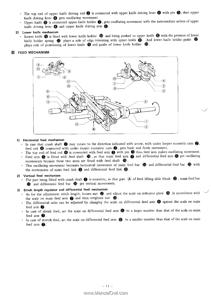
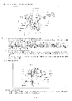
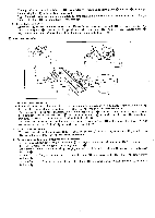
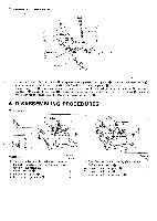
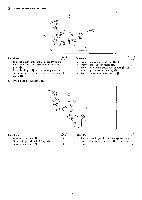
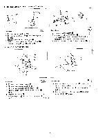
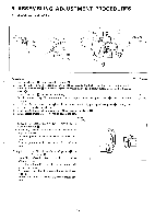
The top end of upper knife driving rod @ is connected with upper knife driving lever 0 with pin @, then upper knife driving lever 0 gets oscillating movement. Upper knife 0 is connected upper knife holder ID, gets oscillating movement with the intermediate action of upper knife driving lever 0 and upper knife driving arm (3. 2) Lower knife mechanism • Lower knife 0 is fixed with lower knife holder 0 and being pushed to upper knife 0 with the pressure of lower . knife holder spring plays a role of edge trimming with upper knife 0. And lower knife holder guide plays role of positioning of lower knife @ and guide of lower knife holder A FEED MECHANISM ti C5) 0 I © 1) Horizontal feed mechanism In case that crank shaft @ may rotate to the direction indicated with arrow, with under looper eccentric cam @, feed rod 0 connected with under looper eccentric cam @, gets back and forth movement. ® , • The top end of feed rod 0 is connected with feed arm with pin thus feed arm makes oscillating movement. • Feed arm @ is fitted with feed shaft so that main feed arm Q and differential feed arm @ get oscillating movements because these two arms are fitted with feed shaft . This oscillating movement becomes horizontal movement of main feed bar 0 and differential feed bar 4D with the movements of main feed link 4) and differential feed link @. 2) Vertical feed mechanism • The part being fitted with crank shaft @ is eccentric, so that part Efik) of feed lifting slide block 0 , main feed bar and differential feed bar (I) get vertical movements. 3) Stitch length regulator and differential feed mechanism ® . As for the adjustment stitch length, loosen nut 41 and adjust the scale on indicator plate the scale on main feed arm 0 and then retighten nut in accordance with The differential ratio can be adjusted by changing the scale on differential feed arm @ against the scale on main feed arm 0. In case of shrink feed, set the scale on differential feed arm @ to a larger number than that of the scale on main, feed arm O. In case of stretch feed, set the scale on differential feed arm @ to a smaller number than that of the scale on main feed arm Q. - 11 -
-
 1
1 -
2
-
3
-
4
-
5
-
6
-
7
-
 8
8 -
 9
9 -
 10
10 -
 11
11 -
 12
12 -
 13
13 -
 14
14 -
 15
15 -
 16
16 -
 17
17 -
 18
18 -
19
-
20
-
21
-
22
-
23
-
24
-
25
-
26
-
27
-
28
-
29
-
30
-
31
-
32
-
33
-
34
-
35
-
36
-
37
-
38
-
39
 |
 |