Brother International KE-430D Instruction Manual - English - Page 24
INSTALLATION, < PMD P. C. board >, < Power supply motor P. C. board >, the PMD P. C. board.
 |
View all Brother International KE-430D manuals
Add to My Manuals
Save this manual to your list of manuals |
Page 24 highlights
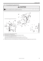
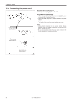
3. INSTALLATION < Power supply motor P. C. board > Press the tab. < PMD P. C. board > The layout for the connector may differ from that shown in the illustration depending on the version of the PMD P. C. board. Connect to connectors with the same color (e.g. black to black). Connectors Machine head memory [7-pin] Upper shaft motor [3-pin] Synchronizer [14-pin] Connectors Work clamp pulse motor [4-pin] Black Thread clamp pulse motor [6-pin] Thread trimmer solenoid [6-pin] Tension release solenoid [4-pin] Y pulse motor [4-pin] Blue X pulse motor [4-pin] White Connection location on power supply motor P. C. board P3 (HEAD-M) P4 (UVW) P5 (SYNC) Connection location on PMD P. C. board P3 (PPM) P4 (BT-PICK) P6 (SOL1) P7 (SOL2) P8 (YPM) P10 (XPM) Cord clamps / Cable ties (4) (6) (6), (7) Cable ties (6), (7) (6), (7) (6), (7) (6), (7) (6), (7) (6), (7) Note: Route the X, Y and work clamp pulse motor harnesses so that they do not touch the PMD P.C. board. 4113M 4415Q 5. Close the cord presser plate (2) in the direction of the white arrow, and secure it by tightening the two screws (1). Note: Close the cord presser plate (2) securely so that no foreign objects, insects or small animals can get inside the control box. 6. Check that the cords do not get pulled, and then gently return the machine head to its original position. 17 KE-430D, BE-438D
-
 1
1 -
2
-
3
-
4
-
5
-
6
-
7
-
8
-
9
-
10
-
11
-
12
-
13
-
14
-
15
-
16
-
17
-
18
-
 19
19 -
 20
20 -
 21
21 -
 22
22 -
 23
23 -
 24
24 -
 25
25 -
 26
26 -
 27
27 -
 28
28 -
 29
29 -
30
-
31
-
32
-
33
-
34
-
35
-
36
-
37
-
38
-
39
-
40
-
41
-
42
-
43
-
44
-
45
-
46
-
47
-
48
-
49
-
50
-
51
-
52
-
53
-
54
-
55
-
56
-
57
-
58
-
59
-
60
-
61
-
62
-
63
-
64
-
65
-
66
 |
 |
