Campbell Scientific CSAT3 CSAT3 3-D Sonic Anemometer - Page 16
Wiring
 |
View all Campbell Scientific CSAT3 manuals
Add to My Manuals
Save this manual to your list of manuals |
Page 16 highlights
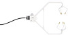
CSAT3 Three Dimensional Sonic Anemometer FIGURE 4-4. CSAT3 coordinate system and original noncaptive mounting hardware (s/n 0107 to 0630) 4.3 Leveling Over flat level terrain, adjust the anemometer head so that the bubble within the level is in the bullseye. Over sloping terrain, adjust the anemometer head so that the horizontal surface that the bubble level is mounted on is parallel to the terrain. Firmly grasp the sonic anemometer block, loosen the bolt underneath the block, and adjust the head accordingly. Finally, tighten the bolt with a 9/16" wrench. 4.4 Fine Wire Thermocouple A fine wire thermocouple (model FW05 and FWC-L35) can be mounted to the side of the anemometer block to measure temperature fluctuations. Attach the female connector from the FWC-L35 to the side of the anemometer with the short screw (#2-56 0.437", p/n 3514) that was provided with the thermocouple cover. Insert the male connector of the FW05 into the female connector of the FWC-L35. Finally, attach the thermocouple cover to the anemometer block, using the thumb screw, so that both the FW05 and FWC-L35 connectors are covered. 5. Wiring There are four military style connectors on the CSAT3 electronics box. They are labeled as +12V SDM, RS-232, Transducer Head, and Analog Output. Connect the cable from the anemometer head to the electronics box labeled Transducer Head. The anemometer head cable is 2.13 m (7 ft) in length. Each of the signal cables is 7.62 m (25 ft) in length. Connect the appropriate signal cable to the electronics box. See the TABLE 5-1 through TABLE 5-8 for details on the wire color scheme. 8
-
 1
1 -
2
-
3
-
4
-
5
-
6
-
7
-
8
-
9
-
10
-
 11
11 -
 12
12 -
 13
13 -
 14
14 -
 15
15 -
 16
16 -
 17
17 -
 18
18 -
 19
19 -
 20
20 -
 21
21 -
22
-
23
-
24
-
25
-
26
-
27
-
28
-
29
-
30
-
31
-
32
-
33
-
34
-
35
-
36
-
37
-
38
-
39
-
40
-
41
-
42
-
43
-
44
-
45
-
46
-
47
-
48
-
49
-
50
-
51
-
52
-
53
-
54
-
55
-
56
-
57
-
58
-
59
-
60
-
61
-
62
-
63
-
64
-
65
-
66
-
67
-
68
-
69
-
70
-
71
-
72
 |
 |
