Canon CINE-SERVO 17-120mm T2.95-3.9 EF User Manual - Page 40
Display Switch, Display, Control key
 |
View all Canon CINE-SERVO 17-120mm T2.95-3.9 EF manuals
Add to My Manuals
Save this manual to your list of manuals |
Page 40 highlights
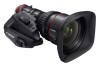
1 NOMENCLATURE 1 NOMENCLATURE 3 2 1 IRIS AM 4 5 6 8 RET 7 7㨤 CN7x 17 KAS S/E1 AUX MEMIO 㧹 10 12 13 15 14 16 22 9 17 18 18 REMOTE1VIMRRETAUMNAOLUTE. 2/SERVO FOCUS REMOTE3 MANU. SERVO ZOOM 11 PL Mount lens Only 20 19 21 Information Display (Digital Drive Unit) ᶃ ᶄ DISPLAY ᶅ 1 Iris Gain Adjusting Trimmer 2 Instant Auto-Iris Switch 3 Iris Operation Mode Change-over Switch 4 Zoom Rocker Seesaw 5 RET Switch (Video Return Switch) 6 MEMO Switch (Memory Switch) 7 AUX 8 Flange Back Lock Screw/Flange Back Adjusting Ring 9 Lens Holder 10 Macro Button/Macro Ring 11 Lens Cable Connector (12-pins) NOTE) PL mount lens only 12 Iris Ring 13 Zoom Lever/Zoom Ring 14 Focus Ring A 15 Focus Ring B 16 Zoom/Focus Operation Change-over Knob 17 Hood Lock Knob 18 Virtual & Zoom Remote/Focus Remote Connectors (20-pin) NOTE) Only Connector ˒ can be used as the iris remote or virtual output port. Use these connectors to connect the control accessory (equipped with a 20 pin connector) for zooming or focusing. Connector ★ has also a function to operate the iris through a focus control accessory and a dedicated cable and a function to interface with various virtual systems. It can output each positioning signal of zoom, focus, and iris. 19 VTR Switch 20 Max. Zoom Speed Volume 21 12-pin Cable 22 Three Screw Holes for Storing the Drive Unit Fixing Screws 1 Display Switch Used to turn the display ON/OFF. 2 Display It turns off if left for 2 minutes without operation. 3 Control key Used to move the cursor up/down/left/right. Press the center to confirm. For the operation of the digital drive unit, refer to the Information Display Manual on the CD-ROM. E2
-
 1
1 -
2
-
3
-
4
-
5
-
6
-
7
-
8
-
9
-
10
-
11
-
12
-
13
-
14
-
15
-
16
-
17
-
18
-
19
-
20
-
21
-
22
-
23
-
24
-
25
-
26
-
27
-
28
-
29
-
30
-
31
-
32
-
33
-
34
-
 35
35 -
 36
36 -
 37
37 -
 38
38 -
 39
39 -
 40
40 -
 41
41 -
 42
42 -
 43
43 -
 44
44 -
 45
45 -
46
-
47
-
48
-
49
-
50
-
51
-
52
-
53
-
54
-
55
-
56
-
57
-
58
-
59
-
60
-
61
-
62
-
63
-
64
-
65
-
66
-
67
-
68
-
69
-
70
-
71
-
72
-
73
-
74
-
75
-
76
-
77
-
78
-
79
-
80
-
81
-
82
-
83
-
84
-
85
-
86
-
87
-
88
-
89
-
90
-
91
-
92
-
93
-
94
-
95
-
96
-
97
-
98
-
99
-
100
-
101
-
102
-
103
-
104
-
105
-
106
-
107
-
108
-
109
-
110
-
111
-
112
-
113
-
114
-
115
-
116
-
117
-
118
-
119
-
120
-
121
-
122
 |
 |
