Cisco SLM2008PT-NA Administration Guide - Page 11
Wall-Mount Option, Connecting the Cisco SLM2008 Switch, Suggested Mounting Hardware
 |
View all Cisco SLM2008PT-NA manuals
Add to My Manuals
Save this manual to your list of manuals |
Page 11 highlights
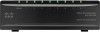
Connecting the Cisco SLM2008 Switch Placement Options 3 Wall-Mount Option NOTE You will need two suitable screws to mount the switch. Cisco is not responsible for damages incurred by insecure wall-mounting hardware. Suggested Mounting Hardware Suggested Mounting Hardware 2.5-3 mm 194478 4-5 mm 1-2 mm To mount the Cisco SLM2008 switch on a wall, follow these steps: STEP 1 Determine where you want to mount the switch. Ensure that the wall you use is smooth, flat, dry, and sturdy. Make sure the location is within reach of the power outlet. STEP 2 Drill two holes in the wall. Make sure the holes are 2 1/2 inches apart. (Optional) Print this page at 100% size, cut along the dotted line and place on the wall to drill precise spacing. Wall Mounting Template 2 ½ inches 194477 Cisco SLM2008 8-Port Gigabit Smart Switch with PD and AC Power Administration Guide 6
-
 1
1 -
2
-
3
-
4
-
5
-
 6
6 -
 7
7 -
 8
8 -
 9
9 -
 10
10 -
 11
11 -
 12
12 -
 13
13 -
 14
14 -
 15
15 -
 16
16 -
17
-
18
-
19
-
20
-
21
-
22
-
23
-
24
-
25
-
26
-
27
-
28
-
29
-
30
-
31
-
32
-
33
-
34
-
35
-
36
-
37
-
38
-
39
-
40
-
41
-
42
-
43
-
44
-
45
-
46
-
47
-
48
-
49
-
50
-
51
-
52
-
53
-
54
-
55
-
56
-
57
-
58
-
59
-
60
-
61
-
62
-
63
-
64
-
65
-
66
 |
 |
