Compaq 8000 Technical Reference Guide: HP Compaq 8000 Elite Series Business De - Page 81
Table 7-6., System Power States, Power, State, System Condition, Consumption, Transition, To S0 by [2]
 |
UPC - 884420665106
View all Compaq 8000 manuals
Add to My Manuals
Save this manual to your list of manuals |
Page 81 highlights
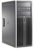
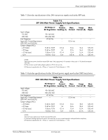
Power and Signal Distribution Table 7-6. System Power States Power State System Condition G0, S0, C0, D0 System fully on. OS and application is running, all components. G1, S1, C1, D1 System on, CPU is executing and data is held in memory. Some peripheral subsystems may be on low power. Monitor is blanked. G1, S2/3, C2, System on, CPU not executing, D2 (Standby/or cache data lost. Memory is suspend) holding data, display and I/O subsystems on low power. G1, S4, D3 (Hibernation) System off. CPU, memory, and most subsystems shut down. Memory image saved to disk for recall on power up. G2, S5, D3cold System off. All components either completely shut down or receiving minimum power to perform system wake-up. PCI and PCIe 3.3V slot power (for wake-up events) can be selectively disabled in BIOS configuration. G3 System off (mechanical). No power to any internal components except RTC circuit. [1] Power Consumption Maximum Low Low Low Minimum None Transition To S0 by [2] N/A < 2 sec after keyboard or pointing device action < 5 sec. after keyboard, pointing device, or power button action
-
 1
1 -
2
-
3
-
4
-
5
-
6
-
7
-
8
-
9
-
10
-
11
-
12
-
13
-
14
-
15
-
16
-
17
-
18
-
19
-
20
-
21
-
22
-
23
-
24
-
25
-
26
-
27
-
28
-
29
-
30
-
31
-
32
-
33
-
34
-
35
-
36
-
37
-
38
-
39
-
40
-
41
-
42
-
43
-
44
-
45
-
46
-
47
-
48
-
49
-
50
-
51
-
52
-
53
-
54
-
55
-
56
-
57
-
58
-
59
-
60
-
61
-
62
-
63
-
64
-
65
-
66
-
67
-
68
-
69
-
70
-
71
-
72
-
73
-
74
-
75
-
 76
76 -
 77
77 -
 78
78 -
 79
79 -
 80
80 -
 81
81 -
 82
82 -
 83
83 -
 84
84 -
 85
85 -
 86
86 -
87
-
88
-
89
-
90
-
91
-
92
-
93
-
94
-
95
-
96
-
97
-
98
-
99
-
100
-
101
-
102
-
103
-
104
-
105
-
106
-
107
-
108
-
109
-
110
-
111
-
112
-
113
-
114
 |
 |
