Compaq dc7700 Hardware Reference Guide - dc7700 CMT - Page 43
CAUTION, Installing a Drive in the Desktop Configuration
 |
View all Compaq dc7700 manuals
Add to My Manuals
Save this manual to your list of manuals |
Page 43 highlights
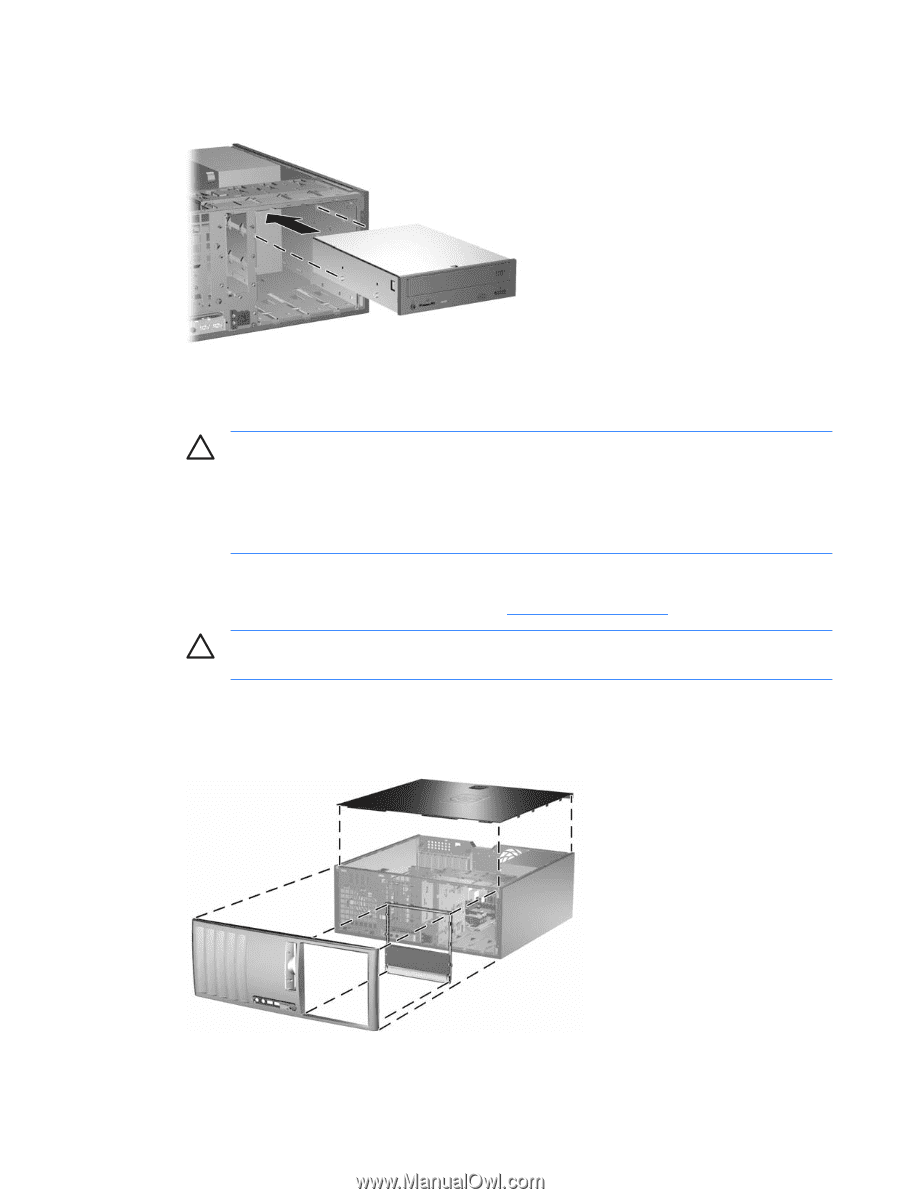
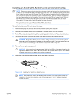
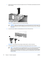
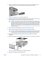
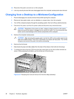
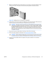
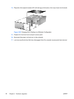
9. Before you reinstall each drive into the chassis, turn the drive so that it is perpendicular to the internal 3.5-inch drive. The drive should be parallel to the green latch drive bracket. Figure 2-25 Installing a Drive in the Desktop Configuration 10. Gently slide the drive into the uppermost available bay until it snaps into place. When the drive is properly inserted, the drivelock will secure it. Repeat this step for each drive. CAUTION The bottom 5.25-inch drive bay has a shorter depth than the upper two bays. The bottom bay supports a drive that is no more than 17 cm (6.7 inches) in depth, including the cables that attach to the back of the drive. Do not try to force a larger drive, such as an optical drive, into the bottom bay. This could cause damage to the drive and the system board. The use of unnecessary force when installing any drive into the drive bay may result in damage to the drive. 11. Reconnect all power and data cables to the drives in the 5.25-inch drive bays. 12. Remove the bezel subpanel as described in the Removing Bezel Blanks section. CAUTION Hold the subpanel straight when you pull it away from the front bezel. Pulling the subpanel away at an angle could damage the pins that align it within the front bezel. 13. Reposition the bezel blanks within the subpanel in the proper orientation for the desktop configuration. 14. Reposition the subpanel (rotate it 90º) with the logo at the bottom, then snap it back into the bezel. Figure 2-26 Changing from a Minitower to a Desktop Configuration 15. Replace the front bezel and computer access panel. ENWW Changing from a Minitower to a Desktop Configuration 37
-
 1
1 -
2
-
3
-
4
-
5
-
6
-
7
-
8
-
9
-
10
-
11
-
12
-
13
-
14
-
15
-
16
-
17
-
18
-
19
-
20
-
21
-
22
-
23
-
24
-
25
-
26
-
27
-
28
-
29
-
30
-
31
-
32
-
33
-
34
-
35
-
36
-
37
-
 38
38 -
 39
39 -
 40
40 -
 41
41 -
 42
42 -
 43
43 -
 44
44 -
 45
45 -
 46
46 -
 47
47 -
 48
48 -
49
-
50
-
51
-
52
-
53
-
54
-
55
-
56
-
57
-
58
-
59
-
60
 |
 |