Craftsman 79194 Operation Manual - Page 5
Minimum 6, 24 cm - line trimmer
 |
View all Craftsman 79194 manuals
Add to My Manuals
Save this manual to your list of manuals |
Page 5 highlights
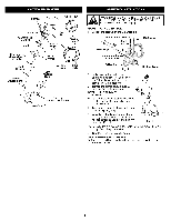
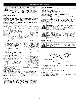
Muffler Spark Plug Oil Fill Plug Shaft Grip On/Off Sto Control D-Handle Craftsman® Convertible TM Coupler Shaft Housing Trimmer Attachment Fuel Cap Starter Rope Grip Cold Starting Lever Throttle Control Line Cutting Blade Air Filter Primer Cover Bulb _Att acCutt inr_gsiheld HassleFree TM UNTIL THE D-HANDLE HAS BEEN ROTATED INTO WOPAERRNAITNINGG: PODSOITNIOONTA(TFFigE. M1P).T TO USETHIS UNIT ADJUSTING THE D-HANDLE 1. Loosen the screws on the D-handle (Fig. 1). On/Off Stop Control Shaft Housing (4) Screws Shaft Grip Minimum 6 (15.24 cm) D-Handle Fig. 1 Bottom Clamp 2. While holding the unit in the operating position (Fig. 2), position the D-handle to the location that provides you the best grip. 3. Tighten the clamp screws evenly, until the D-handle is secure. INSTALL LINE TRIMMER ATTACHMENT NOTE: To make installation easier, place the unit on the ground or on a workbench. 1, Turn knob counterclockwise to loosen coupler (Fig. 15, p. 8). 2. While firmly holding attachment, push it straight into the coupler until the release button snaps into the primary hole (Fig. 16, p. 8). Fig. 2 NOTE: Aligning the release button with the guide recess (Fig. 16, p. 8) will help installation. 3. Turn the knob clockwise to tighten. LINE TRIMMER APPLICATIONS Cutting grass and light weeds; edging; and decorative trimming around trees, fences, etc.
-
 1
1 -
 2
2 -
 3
3 -
 4
4 -
 5
5 -
 6
6 -
 7
7 -
 8
8 -
 9
9 -
 10
10 -
 11
11 -
12
-
13
-
14
-
15
-
16
-
17
-
18
-
19
-
20
-
21
-
22
-
23
-
24
-
25
-
26
-
27
-
28
-
29
-
30
-
31
-
32
-
33
-
34
-
35
-
36
 |
 |
