Craftsman 79194 Operation Manual - Page 8
eye,hearing - trimmer manual
 |
View all Craftsman 79194 manuals
Add to My Manuals
Save this manual to your list of manuals |
Page 8 highlights
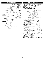
I_b I WpthrioAsutRencNitt.IioNtnoGAr:elwduacytewsheeraiser kyoef,hinejuarrywinhgfoe,onotapnedrbaotidnyg HOLDINTGHETRIMMER Beforeoperatinthgeunit,standinthe operatinpgositio(nFig1. 0)C. hecfkorthe following: • The operator is wearing eye protection and proper clothing • With a slightly-bent right arm, the operator's right hand is holding the shaft grip • The operator's left arm is straight, the left hand holding the assist handle • The unit is at waist level • The cutting attachment is parallel to the ground and easily contacts the grass without the need to bend over TIPS FOR BEST TRIMMING RESULTS • For best trimming results, operate unit with throttle control fully squeezed. • Keep the cutting attachment parallel to Fig. 10 the ground. • Do not force the cutting attachment. Allow the tip of the line to do the cutting, especially along walls. Cutting with more than the tip will reduce cutting efficiency and may overload the engine. • Cut grass over 8 inches (200 mm) by working from top to bottom in small increments to avoid premature line wear or engine drag. • Cutting from right to left improves the unit's cutting efficiency. Clippings are thrown away from the operator. • Slowly move the trimmer into and out of the cutting area at the desired height. Move either in a forward-backward or side-to-side motion. Cutting shorter lengths produces the best results. • Trim only when grass and weeds are dry. • The life of your cutting line is dependent upon: - proper adherence of explained trimming techniques, what - vegetation is cut, and - where vegetation is cut. For example, the line will wear faster when trimming against a foundation wall // as opposed to trimming around a tree. DECORATIVE TRIMMING Decorative trimming is accomplished by removing all vegetation around trees, posts, fences and more. Rotate the whole unit so that the "/_ cutting attachment is at a 30 ° angle to the ground (Fig. 11). _._ _. Fig. 11 USING THE CRAFTSMAN@ CONVERTIBLE TM FEATURE I _,1 and understand the manual that came with the attachment. WFoAllRowNINalGl s:afetyBeinfoforremya°tuionbegcoinntuasininegd awniythaintt.achment' read damage to the unit, shut the unit off before removing or I ,_ I WinsAtaRllNinIgNGa:ttacTh°meanvtosi.d seri°us pers°na' inj ury and You can convert this unit to edge grass. 1. Make sure the unit is turned completely off. 2. Turn the knob counterclockwise to loosen coupler (Fig. 12). 3. Push in the release button (Fig. 13) and twist the shaft 90 ° until the release button snaps into the 90 ° hole (Fig. 12). 4. Turn the knob clockwise to lock the coupler (Fig. 14). 90 ° Edging Hole (Trimmer ®hi Knob Fig. 12 Craftsman® Convertible TM Coupler Primary Hole Release Button Knob Fig. 13 Guide Recess Upper _n _oom Attachment CRAFTSMAN® CONVERTIBLE TM FEATURE Knob Fig. 14 the primary hole only. Using the wrong hole could lead to [_,I CpeArUsoTnIOalNin: juryTohredsaemaattgaechtmo ethnetsunairte. to be snapped into The coupler allows you to convert this unit for use with the following attachments: • Cultivator • Blade Edger • Blower • Brush Cutter • Pruner To Install Attachments release button is fully snapped into the primary hole (Fig. 13), and that the knob (Fig. 14) is securely tightened. NOTE: To make installation easier, place the unit on the ground or on a workbench. 1. Make sure the unit is turned completely off. 2. Turn the knob counterclockwise to loosen the coupler (Fig. 15). 3. While firmly holding the attachment, push it straight into the coupler until the release button (Fig. 16) snaps into the primary hole (Fig. 16). The primary hole is on the opposite side of the coupler from the knob (Fig. 16). Align the release button with the Guide Recess (Fig. 16) to help installation. 4. Turn the knob clockwise to tighten. To Remove Attachments 1. Make sure the unit is turned completely off. 2. Turn the knob counterclockwise to loosen the coupler. 3. Press and hold the release button (Fig. 16). 4. While firmly holding the upper shaft boom (Fig. 17), pull the attachment out of the coupler.
-
 1
1 -
2
-
 3
3 -
 4
4 -
 5
5 -
 6
6 -
 7
7 -
 8
8 -
 9
9 -
 10
10 -
 11
11 -
 12
12 -
 13
13 -
14
-
15
-
16
-
17
-
18
-
19
-
20
-
21
-
22
-
23
-
24
-
25
-
26
-
27
-
28
-
29
-
30
-
31
-
32
-
33
-
34
-
35
-
36
 |
 |
