D-Link DGS-3630-28TC Hardware Installation Guide
D-Link DGS-3630-28TC Manual
 |
View all D-Link DGS-3630-28TC manuals
Add to My Manuals
Save this manual to your list of manuals |
D-Link DGS-3630-28TC manual content summary:
- D-Link DGS-3630-28TC | Hardware Installation Guide - Page 1
- D-Link DGS-3630-28TC | Hardware Installation Guide - Page 2
DGS-3630 Series Layer 3 Stackable Managed Switch Hardware Installation Guide Information in this document is subject to change without notice. Reproduction in any manner whatsoever, without the written permission of D-Link Corporation, is strictly forbidden. Trademarks used in this text: D-Link user - D-Link DGS-3630-28TC | Hardware Installation Guide - Page 3
DGS-3630 Series Layer 3 Stackable Managed Switch Hardware Installation Guide SFP (Mini-GBIC), XENPAK, and XFP Regulatory Compliance Networks pluggable optical modules meet the following regulatory requirements: Class 1. IEC/EN60825-1:2007 2nd Edition or later, - D-Link DGS-3630-28TC | Hardware Installation Guide - Page 4
Readers The DGS-3630 Series Layer 3 Stackable Managed Switch Hardware Installation Guide contains detailed information about the hardware specifications of the switches in this series. It also contains brief information on how to configure and manage a switch in this series. This manual is intended - D-Link DGS-3630-28TC | Hardware Installation Guide - Page 5
DGS-3630 Series Layer 3 Stackable Managed Switch Hardware Installation Guide The product does not operate correctly when the operating instructions the system gets wet contact your trained service provider. Do not push any Instructions. ATTENTION: Risque d'explosion si la batterie est remplacée - D-Link DGS-3630-28TC | Hardware Installation Guide - Page 6
DGS-3630 Series Layer 3 Stackable Managed Switch Hardware Installation Guide CAUTION: Installing systems in a rack without components in the rack. Do not step on or stand on any component when servicing other components in a rack. CAUTION: Never defeat the ground conductor or operate the equipment - D-Link DGS-3630-28TC | Hardware Installation Guide - Page 7
Switch Description ...9 Package Contents...9 Features ...10 2. Hardware Components ...13 DGS-3630-28TC Switch ...13 Front Panel Components...13 LED Indicators ...14 Rear Panel Components ...15 Side Panel Components ...15 DGS-3630-28SC Switch ...16 Front Panel Components...16 LED Indicators ...17 - D-Link DGS-3630-28TC | Hardware Installation Guide - Page 8
DGS-3630 Series Layer 3 Stackable Managed Switch Hardware Installation Guide Connecting to the Switch for the First Time...40 Creating a User Account...40 Configuring the IP Address...41 Connecting to Power Supply (RPS) Cable ...55 Alarm Connector (RJ45) ...56 Warranty & Technical Support...57 viii - D-Link DGS-3630-28TC | Hardware Installation Guide - Page 9
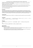
may span great distances. The D-Link DGS-3630 Series includes the following switches: DGS-3630-28TC supports twenty RJ45 ports (10/100/1000 Mbps), four Combo RJ45/SFP ports (10/100/1000 Mbps and 100/1000 Mbps), and four SFP+ ports (10G). DGS-3630-28SC supports twenty SFP ports (100/1000 Mbps - D-Link DGS-3630-28TC | Hardware Installation Guide - Page 10
DGS-3630 Series Layer 3 Stackable Managed Switch Hardware Installation Guide Features This switch is packed with an abundance of networking features that span inside and outside of the traditional Layer 3 framework. The list below highlights the significant protocols and features supported Service - D-Link DGS-3630-28TC | Hardware Installation Guide - Page 11
DGS-3630 Series Layer 3 Stackable Managed Switch Hardware Installation Guide Access Control List (ACL): IP Access List SNMP Trap Web User Interface (Web UI) D-Link Discover Protocol (DDP), and D-Link Network Assistant (DNA) DHCP Server and Client, and DHCP Auto- configuration (IPv4/IPv6) - D-Link DGS-3630-28TC | Hardware Installation Guide - Page 12
DGS-3630 Series Layer 3 Stackable Managed Switch Hardware Installation Guide LLDP-MED MIB, Private MIB, and D-Link Zone Defense. 12 - D-Link DGS-3630-28TC | Hardware Installation Guide - Page 13
Guide 2. Hardware Components This chapter describes the front, rear, and side panel components of all switches in the series. DGS-3630-28TC Switch DGS-3630-28SC Switch DGS-3630-52TC Switch DGS-3630-28TC Switch Front Panel Components The front panel of DGS-3630-28TC configuration speeds and support a - D-Link DGS-3630-28TC | Hardware Installation Guide - Page 14
Guide LED Indicators Located on the front panel of this switch are LED indicators: Power, Console, RPS, Fan Err, USB, MGMT, Link/Act indicators for all the ports, and Stack ID. LED Power Console RPS Fan Err USB MGMT Link/Act LEDs Stack ID Figure 2-2 LED indicators for the DGS-3630-28TC - D-Link DGS-3630-28TC | Hardware Installation Guide - Page 15
LED DGS-3630 Series Layer 3 Stackable Managed Switch Hardware Installation Guide Description The letter 'h' will be an outlet for an external redundant power supply. Figure 2-3 Rear panel view of the DGS-3630-28TC Components that can be found on the rear panel of this switch are listed in - D-Link DGS-3630-28TC | Hardware Installation Guide - Page 16
Guide Figure 2-4 Side panels of the DGS-3630-28TC DGS-3630-28SC Switch Front Panel Components The front panel of DGS-3630-28SC features a variety of LED indicators and ports. Figure 2-5 Front panel view of the DGS-3630-28SC images and configuration files wire-speeds and support a wide collection - D-Link DGS-3630-28TC | Hardware Installation Guide - Page 17
Guide LED Indicators Located on the front panel of this switch are LED indicators: Power, Console, RPS, Fan Err, USB, MGMT, Link/Act indicators for all the ports, and Stack ID. LED Power Console RPS Fan Err USB MGMT Link/Act LEDs Stack ID Figure 2-6 LED indicators for the DGS-3630-28SC - D-Link DGS-3630-28TC | Hardware Installation Guide - Page 18
LED DGS-3630 Series Layer 3 Stackable Managed Switch Hardware Installation Guide Description automatically by the system. The outlet for an external redundant power supply. Figure 2-7 Rear Panel view of the DGS-3630-28SC Components that can be found on the rear panel of this switch are listed in - D-Link DGS-3630-28TC | Hardware Installation Guide - Page 19
Guide Figure 2-8 Side panels of the DGS-3630-28SC DGS-3630-52TC Switch Front Panel Components The front panel of DGS-3630-52TC features a variety of LED indicators and ports. Figure 2-9 Front panel view of the DGS-3630 Mbps and 1 Gbps wire-speeds and support a wide collection of SFP transceivers. - D-Link DGS-3630-28TC | Hardware Installation Guide - Page 20
DGS-3630 Series Layer 3 Stackable Managed Switch Hardware Installation Guide LED Power Console RPS Fan Err Link/Act LEDs no link or activity. This 7-segment LED can display numbers from 1 to 9 and the following letters H, h, E, and G. The stacking ID (1 to 9) can be assigned manually by the user or - D-Link DGS-3630-28TC | Hardware Installation Guide - Page 21
DGS-3630 Series Layer 3 Stackable Managed Switch Hardware Installation Guide Components that can be found on the place. This LED will be off when there is no link present or when this interface was shut down from within the Switch's configuration. Please refer to the "LED Indicators" section in the - D-Link DGS-3630-28TC | Hardware Installation Guide - Page 22
DGS-3630 Series Layer 3 Stackable Managed Switch Hardware Installation Guide Side Panel Components The side panels of this switch contain heat vents, fans, and rack-mounting screw which could lead to system failure or even severely damaged components. Figure 2-12 Side panels of the DGS-3630-52TC 22 - D-Link DGS-3630-28TC | Hardware Installation Guide - Page 23
DGS-3630 Series Layer 3 Stackable Managed Switch Hardware Installation Guide Switch without a Rack This section is used to guide the user through installing the Switch in an area other than the Switch on a sturdy, level surface that can support the weight of the Switch (see the Weight section - D-Link DGS-3630-28TC | Hardware Installation Guide - Page 24
DGS-3630 Series Layer 3 Stackable Managed Switch Hardware Installation Guide Installing the Switch in a Standard 19" Rack This section is used to guide the user various other networking devices to this switch that do not support the standard RJ45 wiring connection. These ports are generally used to - D-Link DGS-3630-28TC | Hardware Installation Guide - Page 25
DGS-3630 Series Layer 3 Stackable Managed Switch Hardware Installation Guide used to connect devices to the Switch SFP+ ports. Figure 3-4 Inserting transceivers into the transceiver ports The SFP+ ports also support other transceiver form factors like SFP and SFP+ transceivers. A complete list of SFP - D-Link DGS-3630-28TC | Hardware Installation Guide - Page 26
DGS-3630 Series Layer 3 Stackable Managed Switch Hardware Installation Guide Figure 3-5 Insert Tie Wrap into the Switch 2. Plug the AC power cord into the power socket of the Switch. Figure 3-6 Connect the power cord to - D-Link DGS-3630-28TC | Hardware Installation Guide - Page 27
DGS-3630 Series Layer 3 Stackable Managed Switch Hardware Installation Guide Figure 3-7 Slide the Retainer through the Tie Wrap 4. Circle the tie of the retainer around the power cord and into the locker of the retainer. Figure 3-8 Circle around the power cord 27 - D-Link DGS-3630-28TC | Hardware Installation Guide - Page 28
DGS-3630 Series Layer 3 Stackable Managed Switch Hardware Installation Guide 5. Fasten the tie of the retainer until the power cord is secured. Figure 3-9 Secure the power cord Installing the Redundant Power Supply (RPS) The Redundant - D-Link DGS-3630-28TC | Hardware Installation Guide - Page 29
Installation Guide Figure 3-10 Connecting a DGS-3630 an RPS is present and now in operation. No software configuration is required. NOTE: See the DPS-500A and DPS-500DC hold up to two RPS units. NOTE: This rack-mount chassis supports the following RPS units: DPS-500A and DPS-500DC. The following - D-Link DGS-3630-28TC | Hardware Installation Guide - Page 30
DGS-3630 Series Layer 3 Stackable Managed Switch Hardware Installation Guide Figure 3-12 Install the DPS-800 in an Equipment Rack 30 - D-Link DGS-3630-28TC | Hardware Installation Guide - Page 31
DGS-3630 Series Layer 3 Stackable Managed Switch Hardware Installation Guide 4. Switch Connections Switch to an End port to the Switch via a twisted pair Category 5e UTP/STP cable. Connect a switch supporting an optical fiber uplink to the Switch's SFP/SFP+ ports via fiber optical cabling. Figure - D-Link DGS-3630-28TC | Hardware Installation Guide - Page 32
Guide Switch Stacking The DGS-3630 series supports stacking serviceability, and availability. Duplex Chain - The Duplex Chain topology stacks switches together in a chain-link be configured to support either a 2-port or a 4-port stacking configuration. When the 2-port stacking configuration is - D-Link DGS-3630-28TC | Hardware Installation Guide - Page 33
DGS-3630 Series Layer 3 Stackable Managed Switch Hardware Installation Guide The figure below illustrates how switches can be stacked in a Duplex Chain formation using optical fiber cables connected to SFP+ transceivers or DAC with SFP+ connectors where the 2-port stacking configuration is used. - D-Link DGS-3630-28TC | Hardware Installation Guide - Page 34
DGS-3630 Series Layer 3 Stackable Managed Switch Hardware Installation Guide The figure below illustrates how switches can be stacked in a Duplex Ring formation using optical fiber cables connected to SFP+ transceivers or DAC with SFP+ connectors where the 2-port stacking configuration is used. - D-Link DGS-3630-28TC | Hardware Installation Guide - Page 35
DGS-3630 Series Layer 3 Stackable Managed Switch Hardware Installation Guide Switch to a Server The Switch is ideal for connecting to a network backbone, server, or server farm. The RJ45 ports operate at a speed of 10/100/ - D-Link DGS-3630-28TC | Hardware Installation Guide - Page 36
information about the Web UI, refer to the DGS-3630 Series Web UI Reference Guide. Connecting to the Console Port The front panel of the Switch provides an RJ45 and a mini-USB console port to connect a remote system for monitoring and configuring the Switch. Both ports require their respective - D-Link DGS-3630-28TC | Hardware Installation Guide - Page 37
DGS-3630 Series Layer 3 Stackable Managed Switch Hardware Installation Guide Connect the male DB9 connector on cable from and into the power receptacle on the back of the Switch. After correctly configuring the terminal settings and re-inserting the power cable, the boot procedure will appear in - D-Link DGS-3630-28TC | Hardware Installation Guide - Page 38
DGS-3630 Series Layer 3 Stackable Managed Switch Hardware Installation Guide Connecting to the Mini-USB Console Port To use the mini-USB console port, the following equipment is needed: A terminal or a computer with a USB 2.0 port - D-Link DGS-3630-28TC | Hardware Installation Guide - Page 39
DGS-3630 Series Layer 3 Stackable Managed Switch Hardware Installation Guide Set the terminal emulation software as follows: from and into the power receptacle on the back of the Switch. After correctly configuring the terminal settings and re-inserting the power cable, the boot procedure will appear - D-Link DGS-3630-28TC | Hardware Installation Guide - Page 40
below). DGS-3630-28TC Gigabit Ethernet Switch Switch> Command Line Interface Firmware: Build 1.00.011 Copyright(C) 2016 D-Link Corporation. All rights reserved. By default, there is no Username and Password configured in the account settings of this switch. This will allow the user to simply - D-Link DGS-3630-28TC | Hardware Installation Guide - Page 41
DGS-3630 Series Layer 3 Stackable Managed Switch Hardware Installation Guide 4. Enter the username NewUser privilege 15 command. Press Enter. This will configure this user account to have Administrative (15) privileges. 5. Enter the line console command to enter the Line Configuration , Link status - D-Link DGS-3630-28TC | Hardware Installation Guide - Page 42
DGS-3630 Series Layer 3 Stackable Managed Switch Hardware Installation Guide Switch#configure configure system features for proper operation, monitor performance, and detect potential problems in the Switch, switch group, or network. Managed devices that support SNMPv3 individual users or groups of - D-Link DGS-3630-28TC | Hardware Installation Guide - Page 43
DGS-3630 Series Layer 3 Stackable Managed Switch Hardware Installation Guide Management Information Base (MIB) A Management management software. In addition to the standard MIB-II, the Switch also supports its own proprietary enterprise MIB as an extended Management Information Base. The proprietary - D-Link DGS-3630-28TC | Hardware Installation Guide - Page 44
DGS-3630 Series Layer 3 Stackable Managed Switch Hardware Installation Guide 6. Web-based Switch Configuration Introduction Logging into the Web UI Web User Interface (Web UI) Introduction Most software functions of the Switch can be managed, configured web browsers are supported: Internet Explorer - D-Link DGS-3630-28TC | Hardware Installation Guide - Page 45
DGS-3630 Series Layer 3 Stackable Managed Switch Hardware Installation Guide NOTE: After a user account was Web User Interface (Web UI) The Web UI provides access to various Switch configuration and management windows. It allows the user to accessible from here. Click the D-Link logo to go to the - D-Link DGS-3630-28TC | Hardware Installation Guide - Page 46
4 DGS-3630 Series Layer 3 Stackable Managed Switch Hardware Installation Guide This area displays a file explorer-type menu tree with all configurable options viewed and configured in this folder. Features regarding the Quality of Service functionality of the Switch can be viewed and configured in - D-Link DGS-3630-28TC | Hardware Installation Guide - Page 47
DGS-3630 Series Layer 3 Stackable Managed Switch Hardware Installation Guide Appendix A - Technical slot only supports FAT16 and FAT32 file system architectures DGS-3630-28TC: 42.4 Watts (Max.), 28.1 Watts (Standby) DGS-3630-28SC: 63.58 Watts (Max.), 30.1 Watts (Standby) DGS-3630-52TC: 62 - D-Link DGS-3630-28TC | Hardware Installation Guide - Page 48
3630-28TC: 95.24 Mpps DGS-3630-28SC: 95.24 Mpps DGS-3630-52TC: 130.95 Mpps 8 Priority Queues per port. Supports 68K MAC addresses (SRM's LAN mode) Supports 1024 Static MAC addresses IPv4: 16K entries IPv6: 7K entries IPv4: 32K entries (SRM's IP mode) IPv6: 16K entries (SRM's IP mode) Supports D-Link - D-Link DGS-3630-28TC | Hardware Installation Guide - Page 49
DGS-3630 Series Layer 3 Stackable Managed Switch Hardware Installation Guide LED Indicators Location Per Device LED Per 10/100/1000 Mbps Port LED per SFP Port LED Power MGMT Console Fan Err RPS USB Stacking ID (7-segment LED) Link/Act/Speed Mode Link/Act Color Green Off Green Off Green Amber Off - D-Link DGS-3630-28TC | Hardware Installation Guide - Page 50
DGS-3630 Series Layer 3 Stackable Managed Switch Hardware Installation Guide Location LED per SFP+ Port LED Link/Act Color Green Amber Off Status Light on (Solid) Light blinking Light on (Solid) Light blinking Light off Description When there is a connection (or link) to a 10 Gbps Ethernet - D-Link DGS-3630-28TC | Hardware Installation Guide - Page 51
DGS-3630 Series Layer 3 Stackable Managed Switch Hardware Installation Guide Feature SFP+ Ports Description DEM-330R DDM) DEM-434XT (10GBASE-ZR, single-mode, 80 km, without DDM) WDM (BiDi) SFP+ Transceivers Supported: DEM-436XT-BXD (10GBASE-LR, single-mode, 20 km, TX: 1330 nm / RX: 1270 nm, - D-Link DGS-3630-28TC | Hardware Installation Guide - Page 52
DGS-3630 Series Layer 3 Stackable Managed Switch Hardware Installation Guide Appendix B - Cables and Connectors Ethernet Cable When connecting the Switch to another switch, a bridge or hub, a straight-through Cat5/5e/6a/7 cable is necessary. Please - D-Link DGS-3630-28TC | Hardware Installation Guide - Page 53
DGS-3630 Series Layer 3 Stackable Managed Switch Hardware Installation Guide Console Cable (RJ45 to RS-232) A console cable is used to connect to the RJ45 console port of the Switch to access the command line - D-Link DGS-3630-28TC | Hardware Installation Guide - Page 54
DGS-3630 Series Layer 3 Stackable Managed Switch Hardware Installation Guide Console Cable (USB to Mini-USB) A console cable is used to connect to the USB console port of the Switch to access the command line - D-Link DGS-3630-28TC | Hardware Installation Guide - Page 55
DGS-3630 Series Layer 3 Stackable Managed Switch Hardware Installation Guide Redundant Power Supply (RPS) Cable When connecting the Switch to a Redundant Power Supply, an RPS cable is necessary. Please review this product for matching cable - D-Link DGS-3630-28TC | Hardware Installation Guide - Page 56
DGS-3630 Series Layer 3 Stackable Managed Switch Hardware Installation Guide Alarm Connector (RJ45) External devices can be connected to the alarm port to either trigger an alarm event or to be the recipient of an - D-Link DGS-3630-28TC | Hardware Installation Guide - Page 57
as the original customer/end user owns the product, or price paid. Any repair or replacement will be rendered by D-Link at an Authorized D-Link Service a Case ID Number from D-Link Technical Support at 1-877-453-5465, who include any manuals or accessories in the shipping package. D-Link will only - D-Link DGS-3630-28TC | Hardware Installation Guide - Page 58
LINK FOR WARRANTY SERVICE) RESULTING FROM THE USE OF THE PRODUCT, RELATING TO WARRANTY SERVICE, OR ARISING OUT OF ANY BREACH OF THIS LIMITED WARRANTY, EVEN IF D-LINK in accordance with the instructions, may cause harmful interference the equipment off and on, the user is encouraged to try to correct - D-Link DGS-3630-28TC | Hardware Installation Guide - Page 59
Product Registration Register your D-Link product online at http://support.dlink.com/register/ Product registration is entirely voluntary and failure to complete or return this form will not diminish your warranty rights. - D-Link DGS-3630-28TC | Hardware Installation Guide - Page 60
U.S. and Canadian customers This guide is only for initial configuration. Please refer to the user manual to learn more or visit http://www.mydlink.com for more information. Also feel free to contact us. U.S. and Canadian customers can contact D-Link Technical Support through our website. USA http - D-Link DGS-3630-28TC | Hardware Installation Guide - Page 61
ÜTZUNG ASSISTANCE TECHNIQUE ASISTENCIA TÉCNICA SUPPORTO TECNICO TECHNISCHE ONDERSTEUNING POMOC TECHNICZNA TECHNICKÁ PODPORA TECHNICKÁ PODPORA TECHNIKAI TÁMOGATÁS TEKNISK SUPPORT TEKNISK SUPPORT TEKNISK STØTTE TEKNINEN TUKI ASSISTÊNCIA TÉCNICA TEHNIČKA PODRŠKA TEHNIČNA PODPORA SUPORT TEHNIC dlink - D-Link DGS-3630-28TC | Hardware Installation Guide - Page 62
.my Philippines - www.dlink.com.ph Vietnam - www.dlink.com.vn Korea customers Tel : +82-2-2028-1810 Monday to Friday 9:00am to 6:00pm Web : http://d-link.co.kr E-mail : [email protected] New Zealand customers Tel: 0800-900-900 24/7 Technical Support Web: http://www.dlink.co.nz E-mail - D-Link DGS-3630-28TC | Hardware Installation Guide - Page 63
12 661 2025 08600 DLINK (for South Africa only) Monday to Friday 8:30am to 9:00pm South Africa Time Web: http://www.d-link.co.za E-mail: [email protected] D-Link Middle East - Dubai, U.A.E. customers Plot No. S31102, Jebel Ali Free Zone South, P.O.Box 18224, Dubai, U.A.E. Tel: +971-4-8809022 Fax - D-Link DGS-3630-28TC | Hardware Installation Guide - Page 64
, Argentine Sq. , Tehran IRAN Postal Code : 1513833817 Tel: +98-21-88880918,19 +98-21-88706653,54 General Inquiries: [email protected] Tech Support: [email protected] Morocco customers M.I.T.C Route de Nouaceur angle RS et CT 1029 Bureau N° 312 ET 337 Casablanca , Maroc Phone : +212 663 72 - D-Link DGS-3630-28TC | Hardware Installation Guide - Page 65
54 49 71 Ext:14 Fax: +961 4 54 49 71 Ext:12 Email: [email protected] Bahrain customers Technical Support: +973 1 3332904 Kuwait customers Technical Support: + 965 22453939 / +965 22453949 Türkiye customers Büyükdere Cad. Ferro Plaza No:155 D: 1 K: 1 Zincirlikuyu / Istanbul Tel: +90 (212) 289-56 - D-Link DGS-3630-28TC | Hardware Installation Guide - Page 66
D-Link. D-Link D-Link D-Link D-Link: 8-800-700-5465 http://www.dlink.ru e-mail: [email protected] Офисы 14 Тел. : +7 (495 22) 80-81-07 E-mail:[email protected] 169 Тэл.: +375 (17) 218-13-65 E-mail: [email protected] 143 7 (727) 378-55-90 E-mail: [email protected] 3 23/5 Հեռ.՝ +374 (10 - D-Link DGS-3630-28TC | Hardware Installation Guide - Page 67
America Por favor revise el número telefónico del Call Center de su país en http://www.dlinkla.com/soporte/call-center Soporte Técnico de D-Link a través de Internet Horario de atención Soporte Técnico en www.dlinkla.com e-mail: [email protected] & [email protected] - D-Link DGS-3630-28TC | Hardware Installation Guide - Page 68
Clientes de Brasil Caso tenha dúvidas na instalação do produto, entre em contato com o Suporte Técnico D-Link. Acesse o site: www.dlink.com.br/suporte - D-Link DGS-3630-28TC | Hardware Installation Guide - Page 69
D-Link D-Link D-Link 0800-002-615 02)6600-0123#8715 9:00到晚上9:00 10:00到晚上7:00 網 站:http://www.dlink.com.tw [email protected] D-Link http://www.dlink.com.tw - D-Link DGS-3630-28TC | Hardware Installation Guide - Page 70
perangkat lunak dan dokumentasi pengguna dapat diperoleh pada situs web D-Link. Dukungan Teknis untuk pelanggan: Tel: +62-21-5731610 Dukungan Teknis D-Link melalui Internet: Email : [email protected] Website : http://support.dlink.co.id 中國客戶 400-629-6688 028)-61317620 http://www - D-Link DGS-3630-28TC | Hardware Installation Guide - Page 71
Reseller's name Telephone Answers to the following questions help us to support your product: 1. Where and how will the product primarily be used Others 4. What network operating system(s) does your organization use ? D-Link LANsmart Novell NetWare NetWare Lite SCO Unix/Xenix PC NFS 3Com 3+Open - D-Link DGS-3630-28TC | Hardware Installation Guide - Page 72
-
 1
1 -
 2
2 -
 3
3 -
 4
4 -
 5
5 -
 6
6 -
 7
7 -
8
-
9
-
10
-
11
-
12
-
13
-
14
-
15
-
16
-
17
-
18
-
19
-
20
-
21
-
22
-
23
-
24
-
25
-
26
-
27
-
28
-
29
-
30
-
31
-
32
-
33
-
34
-
35
-
36
-
37
-
38
-
39
-
40
-
41
-
42
-
43
-
44
-
45
-
46
-
47
-
48
-
49
-
50
-
51
-
52
-
53
-
54
-
55
-
56
-
57
-
58
-
59
-
60
-
61
-
62
-
63
-
64
-
65
-
66
-
67
-
68
-
69
-
70
-
71
-
72
 |
 |