D-Link DGS-3630-28TC Hardware Installation Guide - Page 14
LED Indicators, Located on the front panel of this switch are LED indicators: Power, Console, RPS - manual
 |
View all D-Link DGS-3630-28TC manuals
Add to My Manuals
Save this manual to your list of manuals |
Page 14 highlights
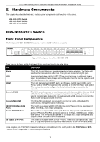
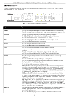
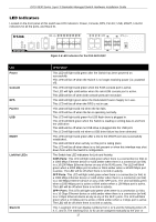
DGS-3630 Series Layer 3 Stackable Managed Switch Hardware Installation Guide LED Indicators Located on the front panel of this switch are LED indicators: Power, Console, RPS, Fan Err, USB, MGMT, Link/Act indicators for all the ports, and Stack ID. LED Power Console RPS Fan Err USB MGMT Link/Act LEDs Stack ID Figure 2-2 LED indicators for the DGS-3630-28TC Description This LED will light solid green after the Switch has been powered on successfully. This LED will be off when the Switch is no longer receiving power (i.e. powered off). This LED will light solid green when the RJ45 console port is active. The LED will light solid amber when the mini-USB console port is active. This LED will be off when both console ports are not active. This LED will light green when the Redundant Powers Supply is in use. This LED will be off when the RPS is not in use. This LED will light solid red when the fan fails. This LED will be off when the fan is operating normally. This LED will light solid green if a USB flash drive is plugged in. This LED will blink green when the Switch is reading or writing data to and from the USB drive. This LED will be off when no USB drive is plugged into the USB port. This LED will light solid red when a USB drive failure has been detected. This LED will light solid green after a link to the MGMT port was successfully established. This LED will blink when activity on this port is taking place. This LED will be off when there is no link present or when this interface was shut down from within the Switch's configuration. The Switch has LED indicators for Link and Activity. RJ45 Ports: This LED will light solid green when there is a connection (or link) to a 1000 Mbps Ethernet device or solid amber when there is a connection (or link) to a 10/100 Mbps Ethernet device on any of the RJ45 ports. The LED will blink green when a 1000 Mbps port is active or blink amber when a 10/100 Mbps port is active. The LED will be off when there is no link or activity. SFP Ports: This LED will light solid green when there is a connection (or link) to a 1000 Mbps Ethernet device or solid amber when there is a connection (or link) to a 100 Mbps Ethernet device on any of the SFP ports. The LED will blink green when a 1000 Mbps port is active or blink amber when a 100 Mbps port is active. The LED will be off when there is no link or activity. SFP+ Ports: This LED will light solid green when there is a connection (or link) to a 10 Gbps Ethernet device or solid amber when there is a connection (or link) to a 1 Gbps Ethernet device at any at any of the SFP+ ports. The LED will blink green when a 10 Gbps port is active or blink amber when a 1 Gbps port is active. The LED will be off when there is no link or activity. This 7-segment LED can display numbers from 1 to 9 and the following letters H, h, E, and G. The stacking ID (1 to 9) can be assigned manually by the user or automatically by the system. The letter 'H' will be displayed if this switch is the master switch in the stack. 14
-
 1
1 -
2
-
3
-
4
-
5
-
6
-
7
-
8
-
 9
9 -
 10
10 -
 11
11 -
 12
12 -
 13
13 -
 14
14 -
 15
15 -
 16
16 -
 17
17 -
 18
18 -
 19
19 -
20
-
21
-
22
-
23
-
24
-
25
-
26
-
27
-
28
-
29
-
30
-
31
-
32
-
33
-
34
-
35
-
36
-
37
-
38
-
39
-
40
-
41
-
42
-
43
-
44
-
45
-
46
-
47
-
48
-
49
-
50
-
51
-
52
-
53
-
54
-
55
-
56
-
57
-
58
-
59
-
60
-
61
-
62
-
63
-
64
-
65
-
66
-
67
-
68
-
69
-
70
-
71
-
72
 |
 |
