D-Link DGS-3630-28TC Hardware Installation Guide - Page 28
Installing the Redundant Power Supply (RPS), DPS-500 Series Redundant Power Supply Unit
 |
View all D-Link DGS-3630-28TC manuals
Add to My Manuals
Save this manual to your list of manuals |
Page 28 highlights
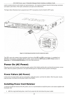
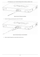
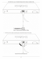
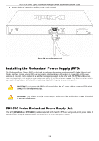
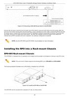
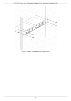
DGS-3630 Series Layer 3 Stackable Managed Switch Hardware Installation Guide 5. Fasten the tie of the retainer until the power cord is secured. Figure 3-9 Secure the power cord Installing the Redundant Power Supply (RPS) The Redundant Power Supply (RPS) is designed to conform to the wattage requirements of D-Link's Ethernet and Gigabit switches. It is an external RPS unit enclosed in solid metal case with sockets to connect AC or DC power sources on one end, and to connect to a switch's internal power supply on the other end. The RPS provides a lowcost, simple solution to the problem of an inadvertent failure of the internal power supply of an Ethernet switch, which can result in the shutdown of that switch, the devices attached to its ports, or an entire network. CAUTION: Do not connect the RPS to AC power before the DC power cable is connected. This might damage the internal power supply. CAUTION: Leave at least 15 cm (6 inches) of space at the rear of the Switch when an RPS is installed to prevent cable damage. DPS-500 Series Redundant Power Supply Unit This RPS (DPS-500A and DPS-500DC) can be connected to the Switch's RPS port using a 14-pin DC power cable. A standard, three-pronged AC power cable connects the RPS to the main power source. 28
-
 1
1 -
2
-
3
-
4
-
5
-
6
-
7
-
8
-
9
-
10
-
11
-
12
-
13
-
14
-
15
-
16
-
17
-
18
-
19
-
20
-
21
-
22
-
 23
23 -
 24
24 -
 25
25 -
 26
26 -
 27
27 -
 28
28 -
 29
29 -
 30
30 -
 31
31 -
 32
32 -
 33
33 -
34
-
35
-
36
-
37
-
38
-
39
-
40
-
41
-
42
-
43
-
44
-
45
-
46
-
47
-
48
-
49
-
50
-
51
-
52
-
53
-
54
-
55
-
56
-
57
-
58
-
59
-
60
-
61
-
62
-
63
-
64
-
65
-
66
-
67
-
68
-
69
-
70
-
71
-
72
 |
 |
