D-Link DGS-3630-28TC Hardware Installation Guide - Page 22
Side Panel Components
 |
View all D-Link DGS-3630-28TC manuals
Add to My Manuals
Save this manual to your list of manuals |
Page 22 highlights
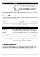
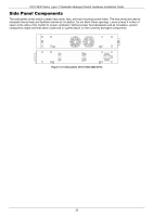
DGS-3630 Series Layer 3 Stackable Managed Switch Hardware Installation Guide Side Panel Components The side panels of this switch contain heat vents, fans, and rack-mounting screw holes. The heat vents are used to dissipate internal heat and facilitate internal air circulation. Do not block these openings. Leave at least 4 inches of space at the sides of the Switch for proper ventilation. Without proper heat dissipation and air circulation, system components might overheat which could lead to system failure or even severely damaged components. Figure 2-12 Side panels of the DGS-3630-52TC 22
-
 1
1 -
2
-
3
-
4
-
5
-
6
-
7
-
8
-
9
-
10
-
11
-
12
-
13
-
14
-
15
-
16
-
 17
17 -
 18
18 -
 19
19 -
 20
20 -
 21
21 -
 22
22 -
 23
23 -
 24
24 -
 25
25 -
 26
26 -
 27
27 -
28
-
29
-
30
-
31
-
32
-
33
-
34
-
35
-
36
-
37
-
38
-
39
-
40
-
41
-
42
-
43
-
44
-
45
-
46
-
47
-
48
-
49
-
50
-
51
-
52
-
53
-
54
-
55
-
56
-
57
-
58
-
59
-
60
-
61
-
62
-
63
-
64
-
65
-
66
-
67
-
68
-
69
-
70
-
71
-
72
 |
 |

DGS-3630 Series Layer 3 Stackable Managed Switch Hardware Installation Guide
22
Side Panel Components
The side panels of this switch contain heat vents, fans, and rack-mounting screw holes. The heat vents are used to
dissipate internal heat and facilitate internal air circulation. Do not block these openings. Leave at least 4 inches of
space at the sides of the Switch for proper ventilation. Without proper heat dissipation and air circulation, system
components might overheat which could lead to system failure or even severely damaged components.
Figure 2-12 Side panels of the DGS-3630-52TC