D-Link DGS-3630-28TC Hardware Installation Guide - Page 34
Duplex Ring, Duplex Ring stacking topology SFP
 |
View all D-Link DGS-3630-28TC manuals
Add to My Manuals
Save this manual to your list of manuals |
Page 34 highlights
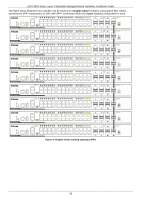
DGS-3630 Series Layer 3 Stackable Managed Switch Hardware Installation Guide The figure below illustrates how switches can be stacked in a Duplex Ring formation using optical fiber cables connected to SFP+ transceivers or DAC with SFP+ connectors where the 2-port stacking configuration is used. Figure 4-4 Duplex Ring stacking topology (SFP+) NOTE: Stacking Input/Output 1 (SIO1) is a logical stacking port pair. SIO2 is also a logical stacking port pair. A logical stacking port pair must always be connected to the same Switch in the stack. Splitting logical stacking port pairs between different Switches in the stack might not guarantee a stable stacking connection. 34
-
 1
1 -
2
-
3
-
4
-
5
-
6
-
7
-
8
-
9
-
10
-
11
-
12
-
13
-
14
-
15
-
16
-
17
-
18
-
19
-
20
-
21
-
22
-
23
-
24
-
25
-
26
-
27
-
28
-
 29
29 -
 30
30 -
 31
31 -
 32
32 -
 33
33 -
 34
34 -
 35
35 -
 36
36 -
 37
37 -
 38
38 -
 39
39 -
40
-
41
-
42
-
43
-
44
-
45
-
46
-
47
-
48
-
49
-
50
-
51
-
52
-
53
-
54
-
55
-
56
-
57
-
58
-
59
-
60
-
61
-
62
-
63
-
64
-
65
-
66
-
67
-
68
-
69
-
70
-
71
-
72
 |
 |

DGS-3630 Series Layer 3 Stackable Managed Switch Hardware Installation Guide
34
The figure below illustrates how switches can be stacked in a
Duplex Ring
formation using optical fiber cables
connected to SFP+ transceivers or DAC with SFP+ connectors where the
2-port
stacking configuration is used.
Figure 4-4 Duplex Ring stacking topology (SFP+)
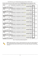
NOTE:
Stacking Input/Output 1 (SIO1) is a logical stacking port pair. SIO2 is also a logical stacking port
pair. A logical stacking port pair must always be connected to the same Switch in the stack. Splitting
logical stacking port pairs between different Switches in the stack might not guarantee a stable stacking
connection.