D-Link DP 300 Manual - Page 11
Installing the Print Server, Power ON Self-Test - print server dp 300u
 |
UPC - 790069212314
View all D-Link DP 300 manuals
Add to My Manuals
Save this manual to your list of manuals |
Page 11 highlights
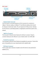
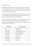
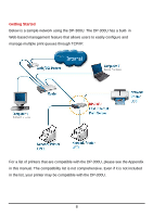
Setting up the DP-300U Installing the Print Server WARNING: Configuration problems may result if the Print Server is powered up without first establishing its network connection. Follow this procedure to avoid complications at the configuration stage. 1. Confirm proper operation of the printers to be connected to the DP-300U. 2. When you have confirmed proper operation of the printer, switch its power OFF. 3. Confirm that your network is operating normally. 4. Connect the DP-300U RJ-45 Connector to the network, using an Ethernet CAT5 cable. 5. While the printer is powered OFF, install the corresponding parallel or USB printer cable to connect the printer's parallel port or USB port to the printer port of the Print Server 6. Switch on the connected printer. 7. Plug the AC power adapter's DC output plug into the DC 5V power socket on the rear panel of the Print Server. 8. Plug the power adapter into a power outlet. This will supply power to the Print Server, as it has no external power switch. The green Power LED on the Print Server's front panel should illuminate steadily, and the Print Server's Self-Test will proceed. Power ON Self-Test Every DP-300U has been factory-tested to operate properly. When the DP-300U is powered ON, it also automatically performs a Self-Test on each of its major components. The final result of the Self-Test is signaled by the state of the LPT/USB LED indicator following the Self-Test. Preliminary to the actual component tests, the five LED indicators are tested to confirm their steady 6
-
 1
1 -
2
-
3
-
4
-
5
-
 6
6 -
 7
7 -
 8
8 -
 9
9 -
 10
10 -
 11
11 -
 12
12 -
 13
13 -
 14
14 -
 15
15 -
 16
16 -
17
-
18
-
19
-
20
-
21
-
22
-
23
-
24
-
25
-
26
-
27
-
28
-
29
-
30
-
31
-
32
-
33
-
34
-
35
-
36
-
37
-
38
-
39
-
40
-
41
-
42
-
43
-
44
-
45
-
46
-
47
-
48
-
49
-
50
-
51
-
52
-
53
-
54
-
55
-
56
-
57
-
58
-
59
-
60
-
61
-
62
-
63
-
64
-
65
-
66
-
67
-
68
-
69
-
70
-
71
-
72
-
73
-
74
-
75
-
76
-
77
-
78
-
79
-
80
-
81
-
82
-
83
-
84
-
85
-
86
-
87
-
88
-
89
-
90
-
91
-
92
-
93
-
94
-
95
-
96
-
97
-
98
-
99
-
100
-
101
-
102
-
103
-
104
-
105
-
106
-
107
-
108
-
109
-
110
-
111
-
112
-
113
-
114
-
115
-
116
-
117
-
118
-
119
-
120
-
121
-
122
-
123
-
124
-
125
-
126
-
127
-
128
-
129
-
130
-
131
-
132
-
133
-
134
-
135
-
136
-
137
-
138
-
139
-
140
-
141
-
142
-
143
-
144
-
145
-
146
-
147
-
148
-
149
-
150
-
151
-
152
 |
 |