D-Link DP 300 Manual - Page 12
LPT/USB LED, Faulty Component
 |
UPC - 790069212314
View all D-Link DP 300 manuals
Add to My Manuals
Save this manual to your list of manuals |
Page 12 highlights
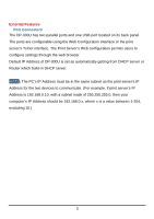
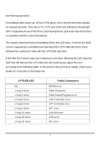
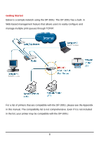
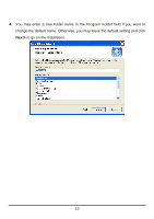
and flashing operation. Immediately after power-up, all five of the green LEDs should illuminate steadily for several seconds. Then the LPT1, LPT2 and USB LED indicators should light OFF. Irregularity of any of the three LEDs during these LED tests may mean there is a problem with the LEDs themselves. The actual component tests immediately follow the LED tests. A normal (no fault) result is signaled by a simultaneous flashing of the LPT/USB LED three times, followed by a quiescent state with the LPT/USB LED dark. If the Self-Test routine traps any component error, then following the LED tests the Self-Test will halt and the LPT/USB LED will continuously signal the error according to the following table. In the event of any such error signal, contact your dealer for correction of the faulty unit. LPT/USB LED On 1 long 3 short 1 long 5 short 1 long 6 short 1 long 8 short 1 long 9 short 1 long 14 short 1 long 18 short 1 long 19 short Faulty Component DRAM error Flash Protected Flash Erase/Program error LAN Controller error LPT Controller error LPT error LAN MII error USB error PCI error 7
-
 1
1 -
2
-
3
-
4
-
5
-
6
-
 7
7 -
 8
8 -
 9
9 -
 10
10 -
 11
11 -
 12
12 -
 13
13 -
 14
14 -
 15
15 -
 16
16 -
 17
17 -
18
-
19
-
20
-
21
-
22
-
23
-
24
-
25
-
26
-
27
-
28
-
29
-
30
-
31
-
32
-
33
-
34
-
35
-
36
-
37
-
38
-
39
-
40
-
41
-
42
-
43
-
44
-
45
-
46
-
47
-
48
-
49
-
50
-
51
-
52
-
53
-
54
-
55
-
56
-
57
-
58
-
59
-
60
-
61
-
62
-
63
-
64
-
65
-
66
-
67
-
68
-
69
-
70
-
71
-
72
-
73
-
74
-
75
-
76
-
77
-
78
-
79
-
80
-
81
-
82
-
83
-
84
-
85
-
86
-
87
-
88
-
89
-
90
-
91
-
92
-
93
-
94
-
95
-
96
-
97
-
98
-
99
-
100
-
101
-
102
-
103
-
104
-
105
-
106
-
107
-
108
-
109
-
110
-
111
-
112
-
113
-
114
-
115
-
116
-
117
-
118
-
119
-
120
-
121
-
122
-
123
-
124
-
125
-
126
-
127
-
128
-
129
-
130
-
131
-
132
-
133
-
134
-
135
-
136
-
137
-
138
-
139
-
140
-
141
-
142
-
143
-
144
-
145
-
146
-
147
-
148
-
149
-
150
-
151
-
152
 |
 |