Dell C9000 Line Cards Networking C9010 Getting Started Guide
Dell C9000 Line Cards Manual
 |
View all Dell C9000 Line Cards manuals
Add to My Manuals
Save this manual to your list of manuals |
Dell C9000 Line Cards manual content summary:
- Dell C9000 Line Cards | Networking C9010 Getting Started Guide - Page 1
Dell Networking C9010 Getting Started Guide Regulatory Model: C9010 - Dell C9000 Line Cards | Networking C9010 Getting Started Guide - Page 2
use of your computer. CAUTION: A CAUTION indicates either potential damage to hardware or loss of data and tells you how to avoid the problem. WARNING: A WARNING indicates a potential for property damage, personal injury, or death. Copyright © 2015 Dell Inc. All rights reserved. This product is - Dell C9000 Line Cards | Networking C9010 Getting Started Guide - Page 3
, refer to these documents: Table 1. C9010 Documentation Information Documentation Hardware installation, power-up instructions, initial Dell Networking Installation Guide for the C9010 software configuration, and network connection Switch Software configuration Dell Networking Configuration - Dell C9000 Line Cards | Networking C9010 Getting Started Guide - Page 4
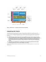
also connect C1048P port extenders as access devices. The C9010 switch supports up to two hundred and forty-eight 1GbE, two hundred and fits into a standard 19"/48.26 cm rack or cabinet. The C9010 chassis supports the following components: • Two full-width route processor modules (RPMs) with four - Dell C9000 Line Cards | Networking C9010 Getting Started Guide - Page 5
Figure 1. C9010 Chassis - Installed Components with Slot Numbers Unpacking the Switch The switch and its accessories ship in a single container. Before unpacking the switch, inspect the container and immediately report any evidence of damage. Verify that you have received your ordered items. If any - Dell C9000 Line Cards | Networking C9010 Getting Started Guide - Page 6
one RPM, three PSU, and nine half-width line card blanks • Two cable management brackets • C9010 Getting Started Guide • Safety and Regulatory Information • Warranty and Support Information • Software License Agreement In addition, you can order the following items: • Up to three additional PSUs for - Dell C9000 Line Cards | Networking C9010 Getting Started Guide - Page 7
airflow, and ventilation. Make sure that the AC power cord can reach the power connector on the front panel of a power supply unit from the power outlet. • Airflow: On the C9010, airflow is from the right to the left side as you face the switch. Hot air is expelled from the left side. Ensure that - Dell C9000 Line Cards | Networking C9010 Getting Started Guide - Page 8
top with the heaviest component at the bottom of the rack. • If the rack is provided with stabilizing devices, install the stabilizers before mounting or servicing the unit in the rack. • If the chassis is shipped with blanks, remove the blanks from each RPM, line card, fan module and PSU slot - Dell C9000 Line Cards | Networking C9010 Getting Started Guide - Page 9
below the chassis. Use the rack bar as a guide to mount the chassis. It is not required to support the weight of the chassis; you can remove it ReadyRails or a rack mount tray to install the C9010, follow the instructions in Installing Dell ReadyRails or Installing a Rack Mount Tray. Then continue - Dell C9000 Line Cards | Networking C9010 Getting Started Guide - Page 10
4. Using a flat-head screwdriver, remove the bracket screws (item 1 in Figure 3) and unscrew the thumb screws to remove the bracket (item 2 in Figure 3) attached to each chassis flange. Figure 3. Removing Brackets from the Chassis 10 Installing the Hardware - Dell C9000 Line Cards | Networking C9010 Getting Started Guide - Page 11
5. Use an equipment lift or two people to lift the empty chassis without blanks (item 1 in Figure 4) and align the rack-mount screw holes on each flange of the chassis with the holes in the equipment rack. Rest the chassis on top of the rack bar (or rack tray, if installed). Slide the chassis so - Dell C9000 Line Cards | Networking C9010 Getting Started Guide - Page 12
6. Verify that the chassis is securely installed in the two rack posts and does not sag. To prevent sagging, support the back of the chassis by using a rack mount shelf or Dell ReadyRails as described in Step 3. Figure 5. Chassis Installed in a 2-Post Rack NOTE: To - Dell C9000 Line Cards | Networking C9010 Getting Started Guide - Page 13
top with the heaviest component at the bottom of the rack. • If the rack is provided with stabilizing devices, install the stabilizers before mounting or servicing the unit in the rack. • If the chassis is shipped with blanks, remove the blanks from each RPM, line card, fan module and PSU slot - Dell C9000 Line Cards | Networking C9010 Getting Started Guide - Page 14
below the chassis. Use the rack bar as a guide to mount the chassis. It is not required to support the weight of the chassis; you can remove it ReadyRails or a rack mount tray to install the C9010, follow the instructions in Installing Dell ReadyRails or Installing a Rack Mount Tray. Then continue - Dell C9000 Line Cards | Networking C9010 Getting Started Guide - Page 15
4. To install the chassis, first insert four cage nuts into the front rack posts at the same height as the thumb screws on each chassis flange. On each post, install the lower cage nut in the top post hole 3 RUs above the rack bar; install the upper cage nut in the bottom post hole 5 RUs above the - Dell C9000 Line Cards | Networking C9010 Getting Started Guide - Page 16
5. Use two people or an equipment lift to align the chassis rack-mount holes with the cage nuts in the front posts (items 1 and 2 in Figure 8). Rest the chassis on top of the rack bar (or rack tray or ReadyRails, if installed). Figure 8. Aligning Rack-Mount Holes with 4-Post Rack Holes 16 - Dell C9000 Line Cards | Networking C9010 Getting Started Guide - Page 17
with cage nuts. Use the rack bar (item 1 in Figure 9) as a guide. First tighten the bottom thumb screw on each flange; then tighten the top thumb non-threaded-hole rack or a tooled method in a threaded-hole rack. Dell ReadyRails support a rack depth of 24 to 30 inches. WARNING: Due to the weight of - Dell C9000 Line Cards | Networking C9010 Getting Started Guide - Page 18
• Front rails for the left and right posts of 2- and 4-post racks (items 5 and 6 in Figure 10) • Rear rails that fit into the left and right front rails on 4-post racks (items 7 and 8 in Figure 10) • Two spacers that allow you to secure the chassis flanges flush on the front rack posts (items 9 and - Dell C9000 Line Cards | Networking C9010 Getting Started Guide - Page 19
7. Rear rail that fits into the left front rail 9. Left spacer 8. Rear rail that fits into the right front rail 10. Right spacer Installing ReadyRails: Tool-less Method for a Non-Threaded-Hole Rack To install ReadyRails using a tool-less method in a non-threaded 4-post rack: 1. Attach a Ready rail - Dell C9000 Line Cards | Networking C9010 Getting Started Guide - Page 20
Figure 11. Installing Tool-less Rails in a Non-Threaded-Hole Rack 20 Installing the Hardware - Dell C9000 Line Cards | Networking C9010 Getting Started Guide - Page 21
2. Attach the chassis rails on the right and left sides of the chassis. • Remove the two chassis rails (items 1 and 2 in Figure 10) from the Dell ReadyRails kit. • Align the holes on the right and left chassis rails with the mounting studs at the bottom of each side of the chassis (orange arrows and - Dell C9000 Line Cards | Networking C9010 Getting Started Guide - Page 22
3. Attach a spacer (items 9 and 10 Figure 10) to the back of each chassis flange. The spacers allow the flanges to be attached flush to each rack post. Place each spacer over the four pins at the back of each chassis flange. Then slide each spacer down so that it locks into place and is flush with - Dell C9000 Line Cards | Networking C9010 Getting Started Guide - Page 23
4. Install two cage nuts (item 2 in Figure 14) in each front post at the desired height of the two thumb screws on each flange. Lift the chassis and slide it into the rails installed in the rack (Figure 14). Tighten the thumb screws in the cage nuts to secure the chassis to the rack. Figure 14. - Dell C9000 Line Cards | Networking C9010 Getting Started Guide - Page 24
2. Using a flat-tipped screwdriver, remove the bracket subassembly and four pins (items 1, 2, and 4 in Figure 15) from the front and rear of each rail. Pull on each subassembly to fully remove it. Figure 15. Installing Tooled Rails in a Threaded-Hole Rack 3. Attach the front of each rail to the - Dell C9000 Line Cards | Networking C9010 Getting Started Guide - Page 25
the use of a rack bar or Dell ReadyRails does not satisfy your C9010 installation requirements, Dell Networking recommends using a rack mount tray to support the weight of a C9010 switch in a 2- or 4-post rack. For information about the chassis weight and other technical specification, see Technical - Dell C9000 Line Cards | Networking C9010 Getting Started Guide - Page 26
To install a rack mount tray in a rack, follow the instructions provided with the tray kit. Decide where you want to mount the switch in the rack. Position the tray at that height and tighten it - Dell C9000 Line Cards | Networking C9010 Getting Started Guide - Page 27
2. Attach a grounding cable to the chassis lug by inserting a 6-gauge cable (item 1 in Figure 18). Using a hand-crimping tool (Tyco Electronics 58433-3 or equivalent), crimp the lug (item 2 in Figure 18) so that the cable is held securely. Figure 18. Grounding the Chassis 3. Connect the opposite - Dell C9000 Line Cards | Networking C9010 Getting Started Guide - Page 28
module LED remains green when the chassis is powered up and the fan module is functioning properly. Installing RPMs and Line Cards The C9010 chassis supports up to ten line cards and two route processor modules. WARNING: Always wear an ESD-preventive wrist or foot-heel ground strap when handling an - Dell C9000 Line Cards | Networking C9010 Getting Started Guide - Page 29
different sizes (RPM blanks are full-width); be sure to install the correct blank panel in each empty slot. • RPMs are hot-swappable. The C9010 supports high availability. • If your system uses two RPMs, both RPMs must have the same software image. Installing the Hardware 29 - Dell C9000 Line Cards | Networking C9010 Getting Started Guide - Page 30
1. Open the left and right ejector levers (item 1 in Figure 21) on an RPM by pressing in the orange tab (item 2 in Figure 21) and rotating it to the right so that both levers snap into the open position. Figure 21. Extending the RPM Ejector Levers 2. Hold the card assembly by the metal carrier - Dell C9000 Line Cards | Networking C9010 Getting Started Guide - Page 31
10 (item 2 in Figure 22; labelled R0 on the chassis) identifies the slot in which you insert the first RPM. Align the card with the guide and gently slide it into the slot by holding the two ejector levers in the fully open position and pushing the card forward. You should - Dell C9000 Line Cards | Networking C9010 Getting Started Guide - Page 32
card. Figure 23 shows the types of line cards supported in a C9010. Figure 23. Example of Line Cards Supported in the C9010 1. On a full-width line card a line card into any line-card slot. Align the card with the guide in the chassis slot. While holding the ejector lever, press on any convenient - Dell C9000 Line Cards | Networking C9010 Getting Started Guide - Page 33
slots at the bottom of the front of the chassis. The C9010 supports only an AC power supply with an IEC 60320 C19 power cable. power grid voltage (100-120 VAC /200-240 VAC). • C9010 power supplies do not support a combination of power grid types. For example, all PSUs must be powered either by 100 - Dell C9000 Line Cards | Networking C9010 Getting Started Guide - Page 34
Figure 24. Installing the First Power Supply Installing the Cable Management System To organize network cables and minimize the obstruction from cables when you insert, remove, and view chassis components, you can install a cable management system on the front of the chassis. Using the cable - Dell C9000 Line Cards | Networking C9010 Getting Started Guide - Page 35
The cable management system consists of two brackets (items 1 and 2 in Figure 25) and is shipped as part of the C9010 base configuration. Figure 25. Cable Management System NOTE: Dell Networking recommends that you install the cable management system after you install the chassis in a rack and all - Dell C9000 Line Cards | Networking C9010 Getting Started Guide - Page 36
To install the cable management system, mount both brackets on the right and left sides of the chassis: 1. Align the openings on the inside of a bracket with the pins (item 1 in Figure 26) and thumb screws on each chassis flange. Figure 26. Installing Cable Management Brackets on the Chassis - Dell C9000 Line Cards | Networking C9010 Getting Started Guide - Page 37
Figure 27. Cable Management Brackets Installed on Chassis 3. To open part of a cable bracket, pull one of the latches forward so that it swings down. 4. To remove a cable bracket, push up the blue button located in the center of a bracket to release it. When you cable C9010 ports, be sure not to - Dell C9000 Line Cards | Networking C9010 Getting Started Guide - Page 38
temperature around the unit (which may be higher than the room temperature) is within the limits specified for the C9010. The supported operational temperature is 32° to 113°F (0°C to 45°C). For more detailed environment requirements, see Technical Specifications. • The airflow into the vents - Dell C9000 Line Cards | Networking C9010 Getting Started Guide - Page 39
and the Simple Network Management Protocol (SNMP). For more information about these options, see the Dell Networking Command Line Reference and Configuration Guides for the C9000 Series. When the C9010 successfully powers up or reloads: • RPM LEDs display system status and management port activity - Dell C9000 Line Cards | Networking C9010 Getting Started Guide - Page 40
LED Color / Description RJ-45 Management • Ethernet port: Link LED • (left LED below port) • Off - No data link activity Solid green - Link is up and operating at maximum port speed; if autonegotiated, port is operating at 1G. Solid amber - Link is up and operating at lower speed; if auto- - Dell C9000 Line Cards | Networking C9010 Getting Started Guide - Page 41
LED Color / Description • Flashing amber - Error condition or reload in progress Figure 29. 1/10GbE SFP+ Port LEDs 1. 24 1/10GbE SFP+ ports with Link/Activity LEDs (up and down arrows indicate port numbers) 2. Module LED Figure 30. 1/10GbE RJ-45 Port LEDs 1. 24 1/10GbE SFP+ ports with Link/ - Dell C9000 Line Cards | Networking C9010 Getting Started Guide - Page 42
LED Color / Description • Flashing blue - Beacon LED used to locate the module • Flashing amber - Error condition or reload in progress Figure 31. Fan Module LED 1. Fan status LED Table 5. Fan LED LED Fan status Color / Description • Solid green - Normal operation; fan module is receiving - Dell C9000 Line Cards | Networking C9010 Getting Started Guide - Page 43
receiving power, but DC output is disabled. Switch on the PSU is in the OFF (down) position. • Off - PSU is receiving power outside of the supported range and is not operational. Installing the Hardware 43 - Dell C9000 Line Cards | Networking C9010 Getting Started Guide - Page 44
and monitor your system, refer to the Dell Networking Configuration Guide for the C9000 Series. For the latest documentation and firmware updates, refer to the Dell Support website at http://www.dell.com/support. Connecting a Console Monitor To perform the initial software configuration, connect - Dell C9000 Line Cards | Networking C9010 Getting Started Guide - Page 45
RJ-45 Console Access The RJ-45 console port is an asynchronous serial port. If you connect a console to this port, it must support asynchronous transmission. NOTE: Before connecting a console, be sure that a terminal emulation program is already installed on your PC console. 1. Install an RJ-45 - Dell C9000 Line Cards | Networking C9010 Getting Started Guide - Page 46
Pin Serial Input/Output 5 GND - 6 RxD Input 7 DSR Input 8 NC (unused) - RJ-45 Console Access with a DB-9 Adapter You can connect to the console through the RJ-45 console port using an RJ-45 to RJ-45 rollover cable and an RJ-45 to DB-9 female DTE adapter (labeled TERMINAL) to a terminal - Dell C9000 Line Cards | Networking C9010 Getting Started Guide - Page 47
for your USB-to-serial console cable kit. For assistance, contact Dell Networking Technical Support. 3. Connect the USB-A end of cable into an available USB port on the Internet, refer to the Dell Networking C9000 Series Configuration Guide. To perform the initial software configuration, gather the - Dell C9000 Line Cards | Networking C9010 Getting Started Guide - Page 48
• Telnet password • Switch IP address • Subnet mask (IP netmask) • Default gateway (router) Command Modes After you install the hardware and the boot process completes, the console monitor displays the CLI prompt for the EXEC command mode. To configure the switch, you must move linearly through - Dell C9000 Line Cards | Networking C9010 Getting Started Guide - Page 49
RPM for remote management. The RJ-45 network management port is located on the left side of the RPM as you face the chassis. Use a supported RJ-45 cable for a network connection. Figure 34. RJ-45 Network Management Port 1. RJ-45 network management port Configuring the Software 49 - Dell C9000 Line Cards | Networking C9010 Getting Started Guide - Page 50
about BMP, refer to the Dell Networking Open Automation Guide: Configuration and Command Line Reference. Accessing the Switch Remotely Configuring the Management Port IP Address To access the switch remotely, manually assign IP addresses to the management ports. You can later configure the - Dell C9000 Line Cards | Networking C9010 Getting Started Guide - Page 51
40GbE QSFP+ line card, you can split a single 40GbE QSFP+ port into four 10GbE SFP+ ports using one of the supported breakout cables. For a list of supported optics, contact your Dell Networking representative or reseller. A 40GbE (quad) port must be in a default configuration before you can split - Dell C9000 Line Cards | Networking C9010 Getting Started Guide - Page 52
CONFIGURATION mode Dell(conf)# linecard number port number portmode quad - linecard number port number specifies the line card and 40GbE port to be split. The line card range is 0 to 11; the port range is 0 to 20. - portmode quad configures a 40GbE port to operate in 4x10G mode. For example: Dell( - Dell C9000 Line Cards | Networking C9010 Getting Started Guide - Page 53
initial software configuration on a C9010, you can configure L2/L3 and other software features. For detailed information, refer to the C9000 Series Configuration and CLI Guides. Configuring the Software 53 - Dell C9000 Line Cards | Networking C9010 Getting Started Guide - Page 54
interface. The service tag on a C9010 line card is located on the bottom of the module. • To receive additional kinds of technical support, click Contact Us. On the Contact Information web page, click Technical Support. To access C9000 Series documentation, go to https://www.dell.com/manuals/. To - Dell C9000 Line Cards | Networking C9010 Getting Started Guide - Page 55
Figure 35. C9010 Service Tag Dell Networking Support 55 - Dell C9000 Line Cards | Networking C9010 Getting Started Guide - Page 56
6 Technical Specifications The following tables describe the technical specifications for the C9010 switch. Table 10. Chassis Physical Design Parameter Specifications Height 13.9 inches (35.26 cm) Width 17.4 inches (44.20 cm) Depth Chassis weight 18.0 inches (45.70 cm) 55 lbs (24.95 kg)
-
 1
1 -
 2
2 -
 3
3 -
 4
4 -
 5
5 -
 6
6 -
 7
7 -
8
-
9
-
10
-
11
-
12
-
13
-
14
-
15
-
16
-
17
-
18
-
19
-
20
-
21
-
22
-
23
-
24
-
25
-
26
-
27
-
28
-
29
-
30
-
31
-
32
-
33
-
34
-
35
-
36
-
37
-
38
-
39
-
40
-
41
-
42
-
43
-
44
-
45
-
46
-
47
-
48
-
49
-
50
-
51
-
52
-
53
-
54
-
55
-
56
 |
 |

Dell Networking C9010
Getting Started Guide
Regulatory Model: C9010