Dell C9000 Line Cards Networking C9010 Getting Started Guide - Page 31
Installing a Line Card, C9010 Hardware Description
 |
View all Dell C9000 Line Cards manuals
Add to My Manuals
Save this manual to your list of manuals |
Page 31 highlights
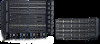
3. The arrow in slot 10 (item 2 in Figure 22; labelled R0 on the chassis) identifies the slot in which you insert the first RPM. Align the card with the guide and gently slide it into the slot by holding the two ejector levers in the fully open position and pushing the card forward. You should feel the backplane connectors on the RPM engage with the chassis backplane. Figure 22. Inserting the First RPM in the Chassis 4. Push in the levers (item 3 in Figure 22) until the thumb tabs pop up and the card is fully inserted in the slot. The ejector levers hide under the card. 5. If the C9010 uses two RPMs, insert the second RPM into slot 11 (labelled R1 on the chassis) below the first RPM by following Steps 1 to 4. 6. If the C9010 uses only one RPM, install a blank panel to cover slot 11. To install the panel, hold the levers and insert the blank to cover the open slot. Push in the lever to secure the blank in place. Installing a Line Card Before you install line cards, review these guidelines: • Install the fan modules before you install line cards in a C9010 switch. • On the C9010, line card slots are labeled 0 to 9. You can insert any line card type into any line card slot. For the location of line-card slot numbers, refer to C9010 Hardware Description. Installing the Hardware 31
-
 1
1 -
2
-
3
-
4
-
5
-
6
-
7
-
8
-
9
-
10
-
11
-
12
-
13
-
14
-
15
-
16
-
17
-
18
-
19
-
20
-
21
-
22
-
23
-
24
-
25
-
 26
26 -
 27
27 -
 28
28 -
 29
29 -
 30
30 -
 31
31 -
 32
32 -
 33
33 -
 34
34 -
 35
35 -
 36
36 -
37
-
38
-
39
-
40
-
41
-
42
-
43
-
44
-
45
-
46
-
47
-
48
-
49
-
50
-
51
-
52
-
53
-
54
-
55
-
56
 |
 |
