Dell Dimension 4100 Dell Dimension 4100 System Solutions Guide - Page 49
Align the notches on the bottom of the module with the crossbars in, the connector.
 |
View all Dell Dimension 4100 manuals
Add to My Manuals
Save this manual to your list of manuals |
Page 49 highlights
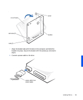
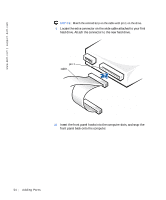
2 Briefly press the power button. Pressing the power button when the computer is not connected to an electrical outlet discharges residual electricity and can help prevent system board damage. 3 Remove the computer cover (see page 42). 4 Press out the securing clip at each end of the memory connector. 5 Align the notches on the bottom of the module with the crossbars in the connector. NOTICE: To avoid breaking the memory module, do not press near the middle of the module. 6 Insert the module straight down into the connector, making sure that it fits into the vertical guides at each end of the connector. Press firmly on the ends until the memory module snaps into place. If you insert the module correctly, the securing clips snap into the cutouts at each end of the module. memory module cutouts (2) securing clips (2) notches (2) connector 6. 5. 4. To remove a memory module, press out the securing clip at each end of the memory connector until the memory module disengages from the connector. Addi ng Part s 49
-
 1
1 -
2
-
3
-
4
-
5
-
6
-
7
-
8
-
9
-
10
-
11
-
12
-
13
-
14
-
15
-
16
-
17
-
18
-
19
-
20
-
21
-
22
-
23
-
24
-
25
-
26
-
27
-
28
-
29
-
30
-
31
-
32
-
33
-
34
-
35
-
36
-
37
-
38
-
39
-
40
-
41
-
42
-
43
-
 44
44 -
 45
45 -
 46
46 -
 47
47 -
 48
48 -
 49
49 -
 50
50 -
 51
51 -
 52
52 -
 53
53 -
 54
54 -
55
-
56
-
57
-
58
-
59
-
60
-
61
-
62
-
63
-
64
-
65
-
66
-
67
-
68
-
69
-
70
-
71
-
72
-
73
-
74
-
75
-
76
-
77
-
78
-
79
-
80
-
81
-
82
-
83
-
84
-
85
-
86
-
87
-
88
-
89
-
90
-
91
-
92
-
93
-
94
-
95
-
96
-
97
-
98
-
99
-
100
-
101
-
102
 |
 |
