Dell Force10 E600i Quick Start Guide
Dell Force10 E600i Manual
 |
View all Dell Force10 E600i manuals
Add to My Manuals
Save this manual to your list of manuals |
Dell Force10 E600i manual content summary:
- Dell Force10 E600i | Quick Start Guide - Page 1
Dell Force10 E300, E600i, and E1200i Systems Quick Start Guide Regulatory Model: E300/E600i TeraScale/E600i ExaScale/ E1200i TeraScale/E1200i ExaScale - Dell Force10 E600i | Quick Start Guide - Page 2
- Dell Force10 E600i | Quick Start Guide - Page 3
Dell Force10 E300, E600i, and E1200i Systems Quick Start Guide Regulatory Model: E300/E600i TeraScale/E600i ExaScale/ E1200i TeraScale/E1200i ExaScale - Dell Force10 E600i | Quick Start Guide - Page 4
to refer to either the entities claiming the marks and names or their products. Dell Inc. disclaims any proprietary interest in trademarks and trade names other than its own. Regulatory Model: E300/E600i TeraScale/E600i ExaScale/E1200i TeraScale/E1200i ExaScale 2011 - 9 P/N 08VJV0 Rev. A00 - Dell Force10 E600i | Quick Start Guide - Page 5
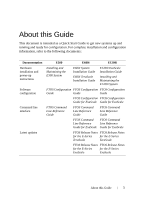
installation and power-up instructions Software configuration Command line interface Latest updates E300 E600i E1200i Installing and Maintaining the E300 System E600i System Installation Guide E600i TeraScale Installation Guide E1200i ExaScale Installation Guide Installing and Maintaining the - Dell Force10 E600i | Quick Start Guide - Page 6
4 About this Guide - Dell Force10 E600i | Quick Start Guide - Page 7
guide assumes all site preparation has been performed before installing the chassis. Installing the Chassis To install an E-Series chassis, Dell Force10 recommends that you complete the installation procedures in the order presented below. NOTE: Unless stated otherwise, the installation instructions - Dell Force10 E600i | Quick Start Guide - Page 8
, install the 23-inch adapters. 2 Using a hand cart, pallet jack, or forklift, align the rack-mount holes with the equipment rack holes, situating the chassis on top of the equipment rack shelf bar. 3 Insert rack mounting screws in the holes that are not obscured by the front shipping cover - Dell Force10 E600i | Quick Start Guide - Page 9
FN00046d Installing E300 Chassis into Rack Installing E600i and 1200i into Rack Attach a Ground Cable to the Chassis NOTE: The rack installation ears are not suitable for grounding. CAUTION: Grounding conductors must be made of copper. Do not use aluminum conductors. NOTE: Coat - Dell Force10 E600i | Quick Start Guide - Page 10
nuts with a nut driver or torque wrench (not to exceed 4 ft/lbs). 7 Connect the opposite end of the grounding cable to the appropriate nearest grounding. E600i TeraScale and ExaScale DC Chassis Ground Step Task 1 Remove one outer nut and one washer from each of the six studs. The inner nut - Dell Force10 E600i | Quick Start Guide - Page 11
(typically the color is green or green with yellow stripe), NOTE: Grounding cables must be terminated only with a ULlisted 2-hole lug with 1/4-inch holes on 3/4-inch spacing. Cable Connector Required for E600i DC High-strand-count conductor All measurements in inches. 0.750" 0.267 diameter - Dell Force10 E600i | Quick Start Guide - Page 12
Tighten the bolt (torque should not exceed 25 inch/lbs). 5 Connect the opposite end of the grounding cable to the nearest appropriate facility grounding post. E1200i TeraScale and ExaScale DC Chassis Ground Step Task 1 Remove one outer nut and one washer from each of the six studs. One nut - Dell Force10 E600i | Quick Start Guide - Page 13
instructions to install AC Power Supply Units (PSUs) and DC Power Entry Modules (PEMs) in each E-Series system. E-Series systems may contain only one type of power module-AC or DC. Unless otherwise stated, each AC and DC power supply for each E-Series system is shipped with a Dell Force10 cables - Dell Force10 E600i | Quick Start Guide - Page 14
the socket-outlet is located/installed near the equipment and is easily accessible. The E300 contains four power supply slots in the rear of the chassis. Each AC power supply contains two LEDs: Status and AC. To install an AC power supply: Step Task 1 Toggle the Standby Switch of the power - Dell Force10 E600i | Quick Start Guide - Page 15
of torque (light torque with a manual screwdriver). Too much torque can damage serviceable. E300 DC Power Modules The E300 supports a minimum of one DC PEM. You must have only one type of power module in the chassis; you cannot install a mixture of power modules. You must provide your own cables - Dell Force10 E600i | Quick Start Guide - Page 16
filled will cause misalignment with screw holes, which might damage the chassis permanently. If you are only installing one PEM, replace the washer from each of the remaining studs. 7 Connect the -48 VDC and Return cables from each PEM to the remote power sources. a Verify that the remote power - Dell Force10 E600i | Quick Start Guide - Page 17
power source (the circuit breaker panel) to the ON position. E600i AC Power Modules The E600i requires a minimum of two AC Power Supplies. Power Supply Input Minimum (N) Redundancy 220 VAC 3 N+1 100 VAC 2 N+1 The chassis has four power supply slots. You may install AC power supplies - Dell Force10 E600i | Quick Start Guide - Page 18
the E600 PEMs to the appropriate branch circuit protection as defined by local electrical codes. You must provide your own cables to connect to a remote power source in your equipment rack. Verify that your cables are: • Rated for at least 80A service to allow for a fully loaded E600i system - Dell Force10 E600i | Quick Start Guide - Page 19
power supplies in the E1200i system, make note of the following: • E1200i ExaScale AC system: The E1200i AC system requires a minimum of 3 AC power supplies install the AC-cord retainer over all power cords. The E1200i AC chassis contains six AC power supply slots. NOTE: If you are installing only - Dell Force10 E600i | Quick Start Guide - Page 20
by local electrical codes. The E1200i DC chassis contains two DC PEM slots. You must provide your own cables to connect to a remote power source in your equipment rack or office. Cables must be sized to meet the following criteria: • Rated for at least 150A service to allow for a fully loaded E1200i - Dell Force10 E600i | Quick Start Guide - Page 21
disconnect shall be provided and shall be easily accessible. Dell Force10 recommends that you use a 150A circuit breaker. Use the PEM. Do not exceed 5 inch/lbs torque. 5 Connect the -48 VDC and Return cables from each PEM to the remote power sources (circuit breakers A and B). a Check that the - Dell Force10 E600i | Quick Start Guide - Page 22
be green. If it is amber, the -48 VDC and Return cables are connected incorrectly or are reversed. Installing RPMs, Line Cards, and Connect your ESD strap to the grounding plug located on the front of the chassis. See Figure 2 for ESD strap connector location. After you remove the original - Dell Force10 E600i | Quick Start Guide - Page 23
pins. Extend the card lever before you insert the card into the slot. 2 Align the SFM with the guide and gently slide it into the slot until you feel the connectors engage with the chassis backplane. 3 Rotate the lever to seat the backplane connectors and card in place. 4 Secure each SFM in - Dell Force10 E600i | Quick Start Guide - Page 24
2 Align the card with the guide and gently slide it into the slot until you feel the connectors engage with the chassis backplane. 3 Rotate the levers to (SFMs) A minimum of four SFMs are required in order for the E600i system to operate properly. There is an additional slot available for a - Dell Force10 E600i | Quick Start Guide - Page 25
pins. Extend the card lever before you insert the card into the slot. 2 Align the SFM with the guide and gently slide it into the slot until you feel the connectors engage with the chassis backplane. 3 Rotate the lever to seat the backplane connectors and card in place. 4 Secure each SFM in - Dell Force10 E600i | Quick Start Guide - Page 26
box and carefully remove the line card from the anti-static packaging. 2 Align the RPM with the guide and gently slide it into the slot until you feel the connectors engage with the chassis backplane. NOTE: Hold the card by the edges. Avoid touching the printed circuit board and connector pins - Dell Force10 E600i | Quick Start Guide - Page 27
until you are ready to supply power to the chassis. Follow the instructions in this section to power up all E-Series TeraScale and ESeries ExaScale systems. Preparation Before you supply power to your chassis, re-inspect your equipment rack and chassis, verify that: • The equipment rack is properly - Dell Force10 E600i | Quick Start Guide - Page 28
unit. 4 The fan tray LED should be green (online). Verify that air is flowing through the chassis. If the fans are not operating properly or air is not flowing through the chassis, power off the chassis at the power module. Ensure that the fan is properly installed. Verify the power source. If - Dell Force10 E600i | Quick Start Guide - Page 29
guide. E300 Your E300 chassis contains one field-replaceable fan tray. Air flows through the system toward the fans and is exhausted on the fan side of the chassis. Air circulates from the right side to the left. Minimum air flow is 665 cubic feet per minute (CFM). E600i TeraScale and E600i ExaScale - Dell Force10 E600i | Quick Start Guide - Page 30
Design Parameter E1200i AC Specifications Height 14 inches (35.6 cm) Width 17.4 inches (44.2 cm) Depth (without cable management system) 24 inches (61 cm) Chassis weight with factory-installed 90 pounds (approx.) (41 kg) components (backplane and air filter) Weight fully loaded (backplane - Dell Force10 E600i | Quick Start Guide - Page 31
Module Power Requirements Module Power Requirement in Watts (in BTU/hour) SFM 55W (188 BTU/hour) E300 RPM 115W (BTU/hour) E300 fan tray 85 W E600i Specifications E600i TeraScale Chassis Physical Design Parameter Specifications Height 28 inches (71.1 cm) Installing the Hardware 29 - Dell Force10 E600i | Quick Start Guide - Page 32
17.4 inches (44.2 cm) Depth (without cable management system) 21.5 inches (54.6 cm) Chassis weight with factory-installed 81 pounds (36.7 14,500 BTU/hour) DC powered: 2800W (9600 BTU/hour) E600i TeraScale Environmental Parameters Parameter Specifications Operating Temperature 32° to 104°F - Dell Force10 E600i | Quick Start Guide - Page 33
W at 100/120 VAC 3,156 W at 200/240 VAC E600i ExaScale Chassis Physical Design Parameter Specifications Height 28 inches (71.1 cm) Width 17.4 inches (44.2 cm) Depth (without cable management system) 21.5 inches (54.6 cm) Chassis weight with factory-installed 81 pounds (36.7 kg) components - Dell Force10 E600i | Quick Start Guide - Page 34
Parameter Maximum for fully loaded chassis Specifications 120 VAC powered: 4705W (16,065 BTU/hour) 200/240 VAC powered: 4250W (14,500 BTU/hour) DC powered: 2800W (9600 BTU/hour) E600i ExaScale Environmental Parameters Parameter Specifications Operating Temperature 32° to 104°F (0° to 40°C) - Dell Force10 E600i | Quick Start Guide - Page 35
inches (93.35 cm) Width 17.40 inches (44.20 cm) 17.40 inches (44.20 cm) Depth (without cable management system) 22.25 inches (56.51 cm) 21.25 inches (53.98 cm) Chassis weight with factory- 139 pounds (approx.) installed components (63.05kg) (backplane and air filter) 97 pounds (approx.) (44 - Dell Force10 E600i | Quick Start Guide - Page 36
VAC (per DC PEM) 150 A E1200i ExaScale Chassis Physical Design Parameter E1200i AC Specifications E1200i DC Specifications Height 42 inches (106.68 cm) 36.75 inches (93.35 cm) Width 17.40 inches (44.20 cm) 17.40 inches (44.20 cm) Depth (without cable management system) 22.25 inches (56.51 - Dell Force10 E600i | Quick Start Guide - Page 37
10-port 10GE line cards) 18,368 BTU/hr 16,446 BTU/hr Minimum (chassis with one 2,313 BTU/hr 10-port 10GE line card) 1,997 BTU/hr E1200i ExaScale Environmental Parameters Parameter Specifications Operating Temperature 32° to 104°F (0° to 40°C) Maximum altitude No performance degradation - Dell Force10 E600i | Quick Start Guide - Page 38
Parameter Maximum Thermal Output Maximum Input Current Maximum System Power Input E1200i AC Specifications 19,449 BTU/hour (5,700 W) (per power supply) 15.0 A @ 200 VAC 12.5 A @ 240 VAC 6.0 KVA @ 200/240 VAC E1200i DC Specifications 17,402 BTU/hour (5,100 W) (per DC PEM) 150 A 36 Installing the - Dell Force10 E600i | Quick Start Guide - Page 39
command moves you up one command mode level. Console Access RPM Ports and Cables There are three ports on the RPM: the Console port, the Auxiliary port connecting with the other ports, refer to your system's Installation Guide. Connecting the Console NOTE: Before starting this procedure, be sure - Dell Force10 E600i | Quick Start Guide - Page 40
/CTS) (for auxiliary port only) Accessing the Console with a DB-9 Adapter You can connect to the console using a RJ-45 to RJ-45 rollover cable and a RJ45 to DB-9 female DTE adapter (labeled "TERMINAL") to a terminal server (for example, PC). Pin Assignments Between the E-Series Console and a DTE - Dell Force10 E600i | Quick Start Guide - Page 41
Console and a DB-25 Adapter Console Port RJ-45 to RJ-45 Rollover Cable RJ-45 to DB-25 Terminal Modem Adapter Server Device Signal RJ-45 Pinout ExaScale Installation Guide for complete information regarding these ports. Default Configuration A version of FTOS is pre-loaded onto the chassis, - Dell Force10 E600i | Quick Start Guide - Page 42
a Host Name The host name appears in the prompt. The default host name is Force10. • Host names must start with a letter and end with a letter or digit. remotely by Telnet. The E-Series systems have a dedicated management port and a management routing table that is separate from the IP routing table - Dell Force10 E600i | Quick Start Guide - Page 43
from IP routes and are only used to manage the system through the management port. Task Command Syntax Command Mode Configure an IPv4 or IPv6 management route to the network from which you are accessing the system. management route {ipv4-address | ipv6- CONFIGURATION address}/mask gateway - Dell Force10 E600i | Quick Start Guide - Page 44
using a DES encryption method. • enable secret is stored in the running/startup configuration in using a stronger, MD5 encryption method. Dell Force10 recommends using the enable secret password. Task Command Syntax Create a password to enable [password | secret] [level level] access EXEC - Dell Force10 E600i | Quick Start Guide - Page 45
When an interface is configured, a switchport automatically places it in the Default VLAN as an untagged interface. All switchports must belong to at least one VLAN, so to remove a switchport from the Default VLAN, you must place it as tagged or untagged in some other VLAN, or remove the switchport - Dell Force10 E600i | Quick Start Guide - Page 46
-id command. Task Command Syntax Configure an IP address and mask on ip address ip-address the interface. mask [secondary] Command Mode INTERFACE Connecting the Chassis to the Network Once you have completed the hardware installation and software configuration, you can connect to your company - Dell Force10 E600i | Quick Start Guide - Page 47
Installing the Software 45 - Dell Force10 E600i | Quick Start Guide - Page 48
46 Installing the Software - Dell Force10 E600i | Quick Start Guide - Page 49
- Dell Force10 E600i | Quick Start Guide - Page 50
Printed in the U.S.A. www.dell.com | support.dell.com
-
 1
1 -
 2
2 -
 3
3 -
 4
4 -
 5
5 -
 6
6 -
 7
7 -
8
-
9
-
10
-
11
-
12
-
13
-
14
-
15
-
16
-
17
-
18
-
19
-
20
-
21
-
22
-
23
-
24
-
25
-
26
-
27
-
28
-
29
-
30
-
31
-
32
-
33
-
34
-
35
-
36
-
37
-
38
-
39
-
40
-
41
-
42
-
43
-
44
-
45
-
46
-
47
-
48
-
49
-
50
 |
 |
Dell Force10
E300, E600i, and E1200i
Systems
Quick Start Guide
Regulatory Model: E300/E600i
TeraScale/E600i ExaScale/
E1200i TeraScale/E1200i
ExaScale