Dell Force10 E600i Quick Start Guide - Page 25
E1200i, R0 for RPMs, and Slot 0 for SFMs.
 |
View all Dell Force10 E600i manuals
Add to My Manuals
Save this manual to your list of manuals |
Page 25 highlights
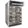
Step Task 1 Remove an SFM from the anti-static packaging. Hold the card by the edges. Avoid touching the printed circuit board and connector pins. Extend the card lever before you insert the card into the slot. 2 Align the SFM with the guide and gently slide it into the slot until you feel the connectors engage with the chassis backplane. 3 Rotate the lever to seat the backplane connectors and card in place. 4 Secure each SFM in place by tightening the captive screw. 5 Continue the process for the remaining SFMs. E1200i RPMs The E1200i system requires the installation of at least one RPM, although two are recommended for redundancy. • Do NOT remove the cards from their protective bags until you are ready to install them in a chassis. • When you are ready to install the cards, unwrap and install one card at a time, starting with the right-most slot (Slot 13 for line cards, Slot R1 for RPMs, and Slot 9 for SFMs) ending with the left-most slot (Slot 0 for line cards, Slot R0 for RPMs, and Slot 0 for SFMs). RPMs are designed to be installed in either the center R0 or R1 slots. Since FTOS searches for an RPM in slot 0 first, Force 10 recommends you install your RPM in slot 0 when only running with one RPM. Do not force RPMs into line card slots. RPMs are keyed differently than line cards to prevent improper installation. Line Cards Your E1200i configuration requires a minimum of one line card. Line cards are hot-swappable. There are 14 line card slots available in the E1200i chassis. A minimum of one line card is required for operation. Line cards are installed in slots 0 through 13. Ports on line cards are numbered from the top, starting from 0. Installing the Hardware 23
-
 1
1 -
2
-
3
-
4
-
5
-
6
-
7
-
8
-
9
-
10
-
11
-
12
-
13
-
14
-
15
-
16
-
17
-
18
-
19
-
 20
20 -
 21
21 -
 22
22 -
 23
23 -
 24
24 -
 25
25 -
 26
26 -
 27
27 -
 28
28 -
 29
29 -
 30
30 -
31
-
32
-
33
-
34
-
35
-
36
-
37
-
38
-
39
-
40
-
41
-
42
-
43
-
44
-
45
-
46
-
47
-
48
-
49
-
50
 |
 |
