Dell Force10 E600i Quick Start Guide - Page 27
Power Up Sequence
 |
View all Dell Force10 E600i manuals
Add to My Manuals
Save this manual to your list of manuals |
Page 27 highlights
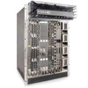
Step Task 3 Rotate the lever to seat the backplane connectors and card in place. 4 Secure each SFM in place by tightening the captive screw. 5 Continue the process for the remaining SFMs. 6 Align any blank panels with the guides and gently slide toward the backplane. Secure each blank panel by tightening the single captive screw. Power Up Sequence WARNING: Make sure that the switch on the remote power source is in the OFF position until you are ready to supply power to the chassis. Follow the instructions in this section to power up all E-Series TeraScale and ESeries ExaScale systems. Preparation Before you supply power to your chassis, re-inspect your equipment rack and chassis, verify that: • The equipment rack is properly secured and grounded. • The chassis is bolted and secured into your equipment rack. • Each power supply module (AC or DC) is properly installed and grounded. • Each power supply module's switch is in the OFF position. • The safety covers are installed on each DC PEM. • Power cables connect to a compliant remote power source. • The fan tray is installed and cannot be removed by pulling on the fan tray handles. • All line cards, RPMs, and SFMs are properly installed and secured. • All chassis slots are filled. Blank panels and covers are installed in all empty slots. Installing the Hardware 25
-
 1
1 -
2
-
3
-
4
-
5
-
6
-
7
-
8
-
9
-
10
-
11
-
12
-
13
-
14
-
15
-
16
-
17
-
18
-
19
-
20
-
21
-
 22
22 -
 23
23 -
 24
24 -
 25
25 -
 26
26 -
 27
27 -
 28
28 -
 29
29 -
 30
30 -
 31
31 -
 32
32 -
33
-
34
-
35
-
36
-
37
-
38
-
39
-
40
-
41
-
42
-
43
-
44
-
45
-
46
-
47
-
48
-
49
-
50
 |
 |
