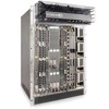
Dell Force10 E600i Quick Start Guide - Page 10
E300 DC PEM Chassis Ground, E600i TeraScale and ExaScale DC Chassis Ground
 |
View all Dell Force10 E600i manuals
Add to My Manuals
Save this manual to your list of manuals |
Page 10 highlights
E300 DC PEM Chassis Ground Step Task 1 Locate the chassis ground connector studs on the PEM front panel. The two studs on the upper left are the ground connection. MAKE GROUND CONNECTION FIRST CAUTION - Use conductors only copper Ground cable, typically green or green with yellow stripes (+) Return cable, typically red (-) -48V cable, typically black Over-current protector switch 2 Remove all nuts and washers from the two ground studs. 3 Apply a coat of anti-oxidant paste to the connector studs. 4 Install the grounding cable. This cable is typically green or green and yellow. NOTE: Termination points require UL-listed 2-hole lug with 1/4inch holes on 3/4-inch spacing. 5 Replace the two washers and nuts on the studs. 6 Secure the nuts with a nut driver or torque wrench (not to exceed 4 ft/lbs). 7 Connect the opposite end of the grounding cable to the appropriate nearest grounding. E600i TeraScale and ExaScale DC Chassis Ground Step Task 1 Remove one outer nut and one washer from each of the six studs. The inner nut should remain tight on the stud, at no more than 25 inch-lbs. 2 Locate the chassis ground connector studs on the PEM front panel. The two bottom studs are the ground connection. 8 Installing the Hardware
-
 1
1 -
2
-
3
-
4
-
 5
5 -
 6
6 -
 7
7 -
 8
8 -
 9
9 -
 10
10 -
 11
11 -
 12
12 -
 13
13 -
 14
14 -
 15
15 -
16
-
17
-
18
-
19
-
20
-
21
-
22
-
23
-
24
-
25
-
26
-
27
-
28
-
29
-
30
-
31
-
32
-
33
-
34
-
35
-
36
-
37
-
38
-
39
-
40
-
41
-
42
-
43
-
44
-
45
-
46
-
47
-
48
-
49
-
50
 |
 |
