Dell Force10 S25N-S50N Installing S50N and S50V Systems
Dell Force10 S25N-S50N Manual
 |
View all Dell Force10 S25N-S50N manuals
Add to My Manuals
Save this manual to your list of manuals |
Dell Force10 S25N-S50N manual content summary:
- Dell Force10 S25N-S50N | Installing S50N and S50V Systems - Page 1
Installing S50N and S50V Systems - Dell Force10 S25N-S50N | Installing S50N and S50V Systems - Page 2
damage to hardware or loss of data if instructions are not followed. WARNING: A WARNING indicates a potential for property damage, personal injury, or death. Information in this publication is subject to change without notice. © 2010 Dell Force10. All rights reserved. Reproduction of these materials - Dell Force10 S25N-S50N | Installing S50N and S50V Systems - Page 3
13 Cabinet Placement 13 Rack Mounting 14 Fans and Airflow 14 Power 14 S50N-DC 14 S50N and S50V 15 Power over Ethernet (PoE) Support 15 Storing Components 16 Tools Required 16 4 Installing the Switch Inserting Optional Modules (10-Gigabit or Stacking 17 Installing the System on a Tabletop - Dell Force10 S25N-S50N | Installing S50N and S50V Systems - Page 4
www.dell.com | support.dell.com The Power Connections on the Switch 30 Installing the Backup DC Power Supply for the S50V 30 Inserting Tandem S50V PSUs into a Rack 31 Connecting the S50V DC-to-DC Cable 32 Installing the Backup DC Power Supply for the S50N 34 DC Components 34 Installing the - Dell Force10 S25N-S50N | Installing S50N and S50V Systems - Page 5
mounting and desk mounting the S50V or S50N switches (and related models, such as S50N-DC), inserting optional modules, and connecting to a power source. Except where noted, descriptions and instructions in this guide apply to all variants of these switches. After you have completed the hardware - Dell Force10 S25N-S50N | Installing S50N and S50V Systems - Page 6
dell.com | support.dell provided and be easily accessible. Dell Force10 recommends the use of a Dell Force10 nvorrichtung muss in der Verdrahtung eingebaut sein. Dell Force10 to the manufacturer's instructions. ACHTUNG - usagees conformement aux instructions du fabricant. NOTE: Other - Dell Force10 S25N-S50N | Installing S50N and S50V Systems - Page 7
CD-ROM contains the S-Series hardware guides and the FTOS and SFTOS files listed above, respectively, except for the Release Notes. The CD-ROMs also have: • MIBs: Files for all SNMP MIBs supported by the software • Data sheets: Links to Dell Force10 product data sheets NOTE: Documentation CD - Dell Force10 S25N-S50N | Installing S50N and S50V Systems - Page 8
www.dell.com | support.dell.com 8 | About this Guide - Dell Force10 S25N-S50N | Installing S50N and S50V Systems - Page 9
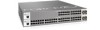
2 System Overview The S50V and S50N models of the Dell Force10 S-Series are stackable, Layer 2 switch/Layer 3 routers with 48 built-in 10/100/ LEDs (SFP Ports 45-48) Stack ID AC XFP49 XFP50 Alarm DC 51 P52 S50-01-GE-48T-V fn00157s50V RJ-45 Console Port Ethernet Ports (10/100/1000) Shared - Dell Force10 S25N-S50N | Installing S50N and S50V Systems - Page 10
dell.com | support.dell.com Equipment The following items are necessary to install the system: • The switch • At least one grounded AC or DC power source per S50V or S50N switch; one or two grounded DC power sources per S50N-DC switch. • Cable (included) to connect the AC power source to the switch - Dell Force10 S25N-S50N | Installing S50N and S50V Systems - Page 11
show commands, and SNMP traps. For details on those options, see the Command Reference and Configuration Guide for your software (FTOS or SFTOS). LED Displays As shown in Figure 2-2 on page 9, the front panel of the switch contains several sets of LEDs: • Stack ID: This is the LED at the far left - Dell Force10 S25N-S50N | Installing S50N and S50V Systems - Page 12
dell.com | support.dell Off Green Blinking Amber AC (on the S50V and S50N) DC1 (on the S50N-DC) Green Amber Off XFP49* Green Blinking Green Off link is established on the port. Indicates the stack ID (sometimes called "switch ID") of the unit. Starting with FTOS 7.8.1.0: • "A" is displayed - Dell Force10 S25N-S50N | Installing S50N and S50V Systems - Page 13
• Power on page 14 • Storing Components on page 16 • Tools Required on page 16 For detailed switch specifications, refer to Chapter , Switch Specifications, on page 47. NOTE: Install the switch into a rack or cabinet before installing any optional components. Site Selection Make sure that the area - Dell Force10 S25N-S50N | Installing S50N and S50V Systems - Page 14
dell.com | support.dell.com Rack Mounting When you prepare your equipment rack, ensure that the rack is earth ground. The equipment rack must be grounded to the same ground point used by the power service S50N and S50V series have an Alarm status LED, which is green when the switch Guide. - Dell Force10 S25N-S50N | Installing S50N and S50V Systems - Page 15
Power Components on page 29. Dell Force10 also offers an external 180W DC power supply for the S50N and S50N-DC models, the same power supply used by the S50. However, the connections differ from those on the S50, so the power supply ships with DC cables to support each model. Rack-mounting hardware - Dell Force10 S25N-S50N | Installing S50N and S50V Systems - Page 16
www.dell.com | support.dell.com The total PoE power budget for the switch is between 320W and 790W, depending on the power sources available. If the external 470W Redundant Power Supply (catalog # S50-01-PSU-V) from Dell Force10 is attached to the Current Sharing terminal (see Chapter , Installing - Dell Force10 S25N-S50N | Installing S50N and S50V Systems - Page 17
4 Installing the Switch To install S50V or S50N systems, Dell Force10 recommends that you complete the installation procedures in 12GbE Stacking 1-port 24GbE Stacking Catalog Number S50-01-10GE-2P S50-01-10GE-2C S50-01-12G-2S S50-01-24G-1S The system supports any of the modules inserted in any - Dell Force10 S25N-S50N | Installing S50N and S50V Systems - Page 18
dell.com | support.dell XFPs on page 44 or the installation instructions that come with the transceiver. CAUTION does not support the use of the cx4-cable-length command, discussed next. CX4 module (catalog number S50-01- ports to 12G stack ports in the switch. The receptacles and cables are the same - Dell Force10 S25N-S50N | Installing S50N and S50V Systems - Page 19
• Two-Post Rack Mounting • Four-Post Rack-mounting with Threaded Rails • Four-Post Rack-mounting with Cage Nuts Two-Post Rack Mounting The switch is shipped with the universal front-mounting brackets (rack ears) attached. Ensure that there is adequate clearance surrounding the rack to permit access - Dell Force10 S25N-S50N | Installing S50N and S50V Systems - Page 20
www.dell.com | support.dell.com Step Task 1 Align the three screw holes of the adjustable rear mounting bracket with the three holes in the unit, and secure the chassis to the front post with two screws. Then secure it to the rear posts with two screws. fn00147s50V 20 | Installing the Switch - Dell Force10 S25N-S50N | Installing S50N and S50V Systems - Page 21
to the chassis using the screws. Top View of Brackets 2 Align and secure the adjustable bracket onto the rear bracket. fn00147f_s50V Align brackets Installing the Switch | 21 - Dell Force10 S25N-S50N | Installing S50N and S50V Systems - Page 22
www.dell.com | support.dell.com Step Task 3 Insert the chassis into the rear of the rack. Position and secure the chassis with two screws into . fn00147a_s50V(4post) 4 Position the cage nuts over the holes on each bracket flange and each rack post. fn00147d_s50V 22 | Installing the Switch - Dell Force10 S25N-S50N | Installing S50N and S50V Systems - Page 23
order in which they come on-line. So, when setting up a new stack, you should have no trouble forcing the identification of the management unit and unit IDs by methodically supplying power to the units in your preferred down, in order to avoid stack management conflicts. Installing the Switch | 23 - Dell Force10 S25N-S50N | Installing S50N and S50V Systems - Page 24
www.dell.com | support.dell.com Using SFTOS Stacking Commands If the switch is running SFTOS, the commands available to manage stacking are described in the Stacking chapters of the SFTOS Command Reference and the SFTOS Configuration Guide. You can execute clear config on the switch to start a - Dell Force10 S25N-S50N | Installing S50N and S50V Systems - Page 25
. Dell Force10 recommends that you mount the switches before you make your stack port connections. Figure 4-3. Switch Stacking Topologies (showing dual-port modules) Ring Topology Cascade Topology Switch 1 A B Switch 1 A B Switch 2 A B Switch 2 A B Switch 3 A B Switch 3 A B While - Dell Force10 S25N-S50N | Installing S50N and S50V Systems - Page 26
Sharing Stack Port A Stack Port B fn00151s25V1 NOTE: These diagrams and instructions use "Stack Port A" and "Stack Port B" for clarifying the connections, but the modules are not labeled. Connecting Three Switches Dell Force10 recommends the ring topology, as outlined above (Figure 4-3 on page - Dell Force10 S25N-S50N | Installing S50N and S50V Systems - Page 27
the order in which they come on-line (see below). The S50V and S50N switches have both AC (3-prong plug receptacle) and DC (-48V terminal-type) choice - AC and DC - the switch will only use the DC source after the AC source fails. In addition, Dell Force10 provides, as an option, an external - Dell Force10 S25N-S50N | Installing S50N and S50V Systems - Page 28
www.dell.com | support.dell.com front left of the switch (see Figure 2-2 on page 9); the left block is matched to the DC2 status LED. You must provide your own cables to connect to the power source. Cables must be sized for 11.5 A service at no more than -48VDC input (per NEC in the United States - Dell Force10 S25N-S50N | Installing S50N and S50V Systems - Page 29
connect the Dell Force10 470W DC Power Supply Unit (PSU) to the Current Sharing terminal of the S50V, the AC and DC are in additive mode, totalling 940W. NOTE: Neither internal nor external S-Series power supplies are field serviceable. If an internal power supply fails, the switch must be replaced - Dell Force10 S25N-S50N | Installing S50N and S50V Systems - Page 30
dell.com | support.dell.com The Power Connections on the Switch The S50V and S50N contain both AC and DC connections. An AC cable is supplied with the switch power supply is oversized to support the Power over Internet (PoE) feature, too large to install in the S50 External Power Shelf. Instead, - Dell Force10 S25N-S50N | Installing S50N and S50V Systems - Page 31
for a single unit. For a tandem installation, see Inserting Tandem S50V PSUs into a Rack on page 31. Step Task 1 Using a #2 Phillips screwdriver, attach the short sides of the rack ears to the front corners of the power supply with the supplied screws. Figure 5-3. Attaching Rack Ears to PSU 2 - Dell Force10 S25N-S50N | Installing S50N and S50V Systems - Page 32
www.dell.com | support.dell.com Step Task 2 Join the two units with the supplied twinning plate (the small, flat, I-beam-shaped metal adapter with four screw holes), using two screws on each side of the plate through the front inside corners of the two switches. Orient the adapter with the - Dell Force10 S25N-S50N | Installing S50N and S50V Systems - Page 33
of the DC-to-DC cable to the DC terminal lugs of the switch (Figure 5-8), with a #2 Phillips screwdriver. Connect the gray wire to FG, red to RTN, brown to -48V. If you connect the blue lead of the Dell Force10 PSU to Current Sharing, you put the PSU in load-sharing mode, which - Dell Force10 S25N-S50N | Installing S50N and S50V Systems - Page 34
www.dell.com | support.dell.com Step Task 2 Insert the plastic plug of the DC-to-DC S50N The Redundant Power Supply Unit (PSU) for the S50N is a 180W AC/DC rectifier. It is less powerful than the S50V PSU, because it does not need to support PoE. This 180W PSU is the same as used for the S50, - Dell Force10 S25N-S50N | Installing S50N and S50V Systems - Page 35
. It is a 2.5RU chassis that can house up to eight PSUs (for up to eight switches). Figure 5-10. Front and Back Views of External Power Shelf (EPS) Figure 5-11. EPS rack ears. Figure 5-12 on page 36 shows the EPS mounted below an S50. For rear-mounting the EPC, slide the EPS into the rack from the - Dell Force10 S25N-S50N | Installing S50N and S50V Systems - Page 36
www.dell.com | support.dell.com continue, as above. Figure 5-12 on page 36 shows screws. Figure 5-13. EPS Front-Mounted (shown below an S50) Inserting an S50N PSU into the EPS The Power Supply Unit (PSU) that supports both the S50 and S50N is an optional, external AC/DC rectifier that provides 180W - Dell Force10 S25N-S50N | Installing S50N and S50V Systems - Page 37
, three individual wires with fork connectors that connect to the DC terminal block in the rear of the S50N (see Figure 5-15). In both cases (S50 and S50N), the DC-DC cable length is 1 meter (39 inches), with, at the end that connects to the PSU, a plastic plug containing two rows of three - Dell Force10 S25N-S50N | Installing S50N and S50V Systems - Page 38
support.dell.com Figure 5-15. DC-DC Cable for S50N Follow the steps below to connect the switch to the PSU: Step Task 1 With the switch unplugged from AC power, connect the DC-DC plug to the switch. Connect the individual leads of the DC-to-DC cable to the DC terminal lugs of the S50N switch - Dell Force10 S25N-S50N | Installing S50N and S50V Systems - Page 39
the external PSU (Figure 5-9). Figure 5-17. DC-to-DC Connection , 3.6A -48V RTN -48V FG S50N fn00153s50N DC-to-DC Cable DC Power Module 3 Tighten the captive screws on the sides of the connector cable separate from the AC connection made directly to the switch. Installing Backup Power | 39 - Dell Force10 S25N-S50N | Installing S50N and S50V Systems - Page 40
40 | Installing Backup Power www.dell.com | support.dell.com - Dell Force10 S25N-S50N | Installing S50N and S50V Systems - Page 41
Figure 6-1. Console Port of S50V 49 arm D 50 51 5 Set your initial console terminal settings to match the default console settings on the switch: • 9600 baud rate • No parity • 8 data bits • 1 stop bit • No flow control (console port only) After establishing a connection, you can modify the - Dell Force10 S25N-S50N | Installing S50N and S50V Systems - Page 42
www.dell.com | support.dell.com Step Task (continued) 4 If you use the console port to download software to the switch, you should raise the console baud rate. If SFTOS is control PoE, see the PoE chapters of the Configuration Guide and Command Reference for your software. 42 | Installing Ports - Dell Force10 S25N-S50N | Installing S50N and S50V Systems - Page 43
specified switch in an S- Redundant Power Supply (catalog # S50-01- XFPs on page 44 The S50N and S50V each have four receptacles switch is running. CAUTION: Before connecting a transceiver to a source, check the receive power of the transceiver with an optical power meter. Generally, Dell Force10 - Dell Force10 S25N-S50N | Installing S50N and S50V Systems - Page 44
www.dell.com | support.dell.com WARNING: Electrostatic discharge (ESD) damage can occur if components are mishandled. Always wear an ESD-preventive wrist or heel ground strap when handling the switch and its components. Step Task 1 Position the SFP so it is in the upright position. (The SFP has - Dell Force10 S25N-S50N | Installing S50N and S50V Systems - Page 45
use a CX4 cable with an XFP port by inserting a CX4 XFP converter (catalog name GP- XFP-1CX4) into the slot. An XFP port does not support the use of the cx4-cable-length command. For details, see Inserting Optional Modules (10-Gigabit or Stacking) on page 17. For enabling ports with - Dell Force10 S25N-S50N | Installing S50N and S50V Systems - Page 46
46 | Installing Ports www.dell.com | support.dell.com - Dell Force10 S25N-S50N | Installing S50N and S50V Systems - Page 47
to the S50V (catalog # S50-01-GE48T-V) and S50N (catalog # S50-01-GE-48T-AC for AC-powered version of S50N; catalog # S50-01-GE-48TDC for S50N-DC). Chassis Physical Design Parameter .5 cm) (standard 1 rack unit - 1RU) Front: 5 inches (12.7 cm) Rear: 5 inches (12.7 cm) Switch Specifications | 47 - Dell Force10 S25N-S50N | Installing S50N and S50V Systems - Page 48
dell.com | support.dell to 158°F (-40° to 70°C) S50N: 531 BTU/Hour S50N-DC: 465 BTU/Hour S50V: 497 meet MIL-STD-810 Telcordia GR-63-CORE S50N: 42.0 dBA at 73.4°F (23°C) @ 115 VAC 3.25 A @ 200/240 VAC S50N: 156W S50N-DC: 136 W S50V: 146W 320W for PoE using 48V to -54Vz S50N-DC: 3.6 A at -48 VDC S50V - Dell Force10 S25N-S50N | Installing S50N and S50V Systems - Page 49
S50N and S50V switches contain a lithium battery. The switch contains no user-serviceable parts. For details on recycling the switch or any of its components, see Product Recycling and Disposal on page 52. Agency Compliance The S50N accordance to the instructions, it may limits. Dell Force10 is not - Dell Force10 S25N-S50N | Installing S50N and S50V Systems - Page 50
www.dell.com | support.dell.com trouble occurs, the user may be required to take corrective actions. WARNING: AC Power cords are for use with Dell Force10 equipment only. Do not use Dell Force10 AC power cords with any unauthorized hardware. Korea (MIC certification) Korea Certification 50 | Switch - Dell Force10 S25N-S50N | Installing S50N and S50V Systems - Page 51
• EN 60825-1 Safety of Laser Products-Part 1: Equipment Classification Requirements and User's Guide • EN 60825-2 Safety of Laser Products-Part 2: Safety of Optical Fibre Communication Systems Fluctuations and Flicker • EN 61000-4-2 ESD • EN 61000-4-3 Radiated Immunity Switch Specifications | 51 - Dell Force10 S25N-S50N | Installing S50N and S50V Systems - Page 52
required by WEEE. For information on Dell Force10 product recycling offerings, see the WEEE Recycling instructions on iSupport at: http://www.force10networks.com/CSPortal20/Support/WEEEandRecycling.pdf. For more information, contact the Dell Force10 Technical Assistance Center (TAC) (see Contacting - Dell Force10 S25N-S50N | Installing S50N and S50V Systems - Page 53
the battery) far enough to provide room for the battery to be lifted above the edge of its retainer, as shown in this photograph. Batteries or packaging for batteries are and treatment, contact your local Dell Force10 representative. Figure 7-2. The European WEEE symbol Switch Specifications | 53 - Dell Force10 S25N-S50N | Installing S50N and S50V Systems - Page 54
www.dell.com | support.dell.com For California: Perchlorate Material - Special handling may apply. See: http://www.dtsc.ca.gov/hazardouswaste/perchlorate California Code of Regulations Title 22, Division 4.5 Chapter 33. Best Management Practices for Perchlorate Materials. 54 | Switch Specifications - Dell Force10 S25N-S50N | Installing S50N and S50V Systems - Page 55
manuals. After you get an account and log in, the available documentation expands to other types, including bug lists, error message decoder, release notes. You can even track your own Dell Force10 inventory. Accessing iSupport Services The URL for iSupport is http://www.force10networks.com/support - Dell Force10 S25N-S50N | Installing S50N and S50V Systems - Page 56
Center How to Contact Dell Force10 TAC Information to Submit When Opening a Support Case Managing Your Case Downloading Software Updates Technical Documentation Contact Information Log in to iSupport at http://www.force10networks.com/support/, and select the Service Request tab. • Your name - Dell Force10 S25N-S50N | Installing S50N and S50V Systems - Page 57
support case. Open a support case by: • Using the Create Service Request form on the iSupport page (see Contacting the Technical Assistance Center on page 56). • Contacting Dell Force10 tech-support.) • Console captures showing the error messages • Console captures showing the troubleshooting - Dell Force10 S25N-S50N | Installing S50N and S50V Systems - Page 58
58 | Technical Support www.dell.com | support.dell.com - Dell Force10 S25N-S50N | Installing S50N and S50V Systems - Page 59
(S50/S50N rectifier) 34 Catalog# SA-01-PSU-V (external rectifier for S25V and S50V) 29 Chassis Physical Design depth 47 height 47 width 47 commands cx4-cable-length 18 inlinepower threshold 16 member 24 movemanagement 24 no member 24 PoE 43 power-budget 16 show logging eventlog 57 show switch 24 - Dell Force10 S25N-S50N | Installing S50N and S50V Systems - Page 60
www.dell.com | support.dell.com E earth ground 14 electromagnetic noise 13 electrostatic discharge 16, 17 Emissions 51 Environmental Parameters 48 ESD 16, 17, 44 Ethernet crossover cable 41 Ethernet - Dell Force10 S25N-S50N | Installing S50N and S50V Systems - Page 61
S50-01-GE-48T-AC (S50N catalog number) 17 S50-01-GE-48T-DC (S50N-DC catalog number) 17 S50-01-GE-48T-V (S50V catalog number) 17 S50N (Cat# S50-01-GE-48T-AC) 9 S50N-DC (Cat# S50-01-GE-48T-DC) 9 S50V (Cat# S50 number, SFP optics 57 serial number, switch 56 Serial Numbers, Locating 56 SFP installation - Dell Force10 S25N-S50N | Installing S50N and S50V Systems - Page 62
.dell.com stack-unit priority command 24 stack-unit provision command 24 stack-unit renumber command 24 Status indicator LEDs 11 status panel LEDs 9, 15 storage guidelines 16 Storing Components 16 straight-through cable 41 support contacts 55 Swapping Units 23 Swapping Units in a Stack 23 switch - Dell Force10 S25N-S50N | Installing S50N and S50V Systems - Page 63
- Dell Force10 S25N-S50N | Installing S50N and S50V Systems - Page 64
Printed in the U.S.A. www.dell.com | support.dell.com
-
 1
1 -
 2
2 -
 3
3 -
 4
4 -
 5
5 -
 6
6 -
 7
7 -
8
-
9
-
10
-
11
-
12
-
13
-
14
-
15
-
16
-
17
-
18
-
19
-
20
-
21
-
22
-
23
-
24
-
25
-
26
-
27
-
28
-
29
-
30
-
31
-
32
-
33
-
34
-
35
-
36
-
37
-
38
-
39
-
40
-
41
-
42
-
43
-
44
-
45
-
46
-
47
-
48
-
49
-
50
-
51
-
52
-
53
-
54
-
55
-
56
-
57
-
58
-
59
-
60
-
61
-
62
-
63
-
64
 |
 |

Installing S50N and
S50V Systems