Dell Force10 S25N-S50N Installing S50N and S50V Systems - Page 14
Rack Mounting, Fans and Airflow, Power, S50N-DC, SFTOS Command Reference, SFTOS Configuration Guide
 |
View all Dell Force10 S25N-S50N manuals
Add to My Manuals
Save this manual to your list of manuals |
Page 14 highlights
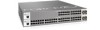
www.dell.com | support.dell.com Rack Mounting When you prepare your equipment rack, ensure that the rack is earth ground. The equipment rack must be grounded to the same ground point used by the power service in your area. The ground path must be permanent. Fans and Airflow Ventilation is side-to-side, with six fans on the left side of the switch. For proper ventilation, position the switch in an equipment rack (or cabinet) with a minimum of five inches (12.7 cm) of clearance around the side intake and exhaust vents. When two S-Series systems are installed side by side, position the two chassis at least 5 inches (12.7 cm) apart to permit proper airflow. The acceptable ambient temperature ranges are listed in Environmental Parameters on page 48. As listed in Table 2-2 on page 12, the front panels of the S50N and S50V series have an Alarm status LED, which is green when the switch is operating within required temperature parameters and all components are operating normally, including fans. The LED is amber when the temperature or components are outside expected parameters, red in a major alarm. The fan speed increases when the temperature reaches 72 degrees C, and decreases to normal speed when the temperature falls to 57 degrees C. The switch never intentionally stops managing traffic. SFTOS logs a temperature warning message when a temperature of 77 degrees C is reached, and logs another message when the temperature returns to normal. The Command Line Interface (CLI) also reports an alarm. Use the show logging command to see the log messages. For details, see the System Logs chapters of the SFTOS Command Reference and SFTOS Configuration Guide. In a stack, each unit has its own temperature monitoring and control. Status logging is identified by unit in the system log. Fan replacement in the field is not offered as an option. Power S50N-DC As shown below, the right side of the S50N-DC contains two terminal blocks for two 150W DC power supply inputs. The terminal blocks are labeled DC1 and DC2, which corresponds to the labels of the status LEDs on the front left of the switch. When both blocks are connected, they act in load-sharing mode with backup capability (one power supply can run the whole system). 14 | Site Preparations
-
 1
1 -
2
-
3
-
4
-
5
-
6
-
7
-
8
-
 9
9 -
 10
10 -
 11
11 -
 12
12 -
 13
13 -
 14
14 -
 15
15 -
 16
16 -
 17
17 -
 18
18 -
 19
19 -
20
-
21
-
22
-
23
-
24
-
25
-
26
-
27
-
28
-
29
-
30
-
31
-
32
-
33
-
34
-
35
-
36
-
37
-
38
-
39
-
40
-
41
-
42
-
43
-
44
-
45
-
46
-
47
-
48
-
49
-
50
-
51
-
52
-
53
-
54
-
55
-
56
-
57
-
58
-
59
-
60
-
61
-
62
-
63
-
64
 |
 |
