Dell Force10 S25N-S50N Installing S50N and S50V Systems - Page 11
System Status, LED Displays
 |
View all Dell Force10 S25N-S50N manuals
Add to My Manuals
Save this manual to your list of manuals |
Page 11 highlights
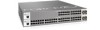
• Expansion slots that accept any combination of the following optional, high-capacity uplink modules: 10GbE XFP (two ports), 10GbE CX4 (two ports), 12G stacking (two ports) or 24G stacking (one port). See Inserting Optional Modules (10-Gigabit or Stacking) on page 17 and Connecting Stack Ports (optional) on page 25. System Status Chassis status information can be derived in several ways, including physical LED displays and boot menu options, both discussed here, along with CLI show commands, and SNMP traps. For details on those options, see the Command Reference and Configuration Guide for your software (FTOS or SFTOS). LED Displays As shown in Figure 2-2 on page 9, the front panel of the switch contains several sets of LEDs: • Stack ID: This is the LED at the far left of the front panel labeled "STACK ID". See Stack ID in Table 2-2 on page 12). For more on stack unit numbering, see Stacking on page 23. • Status indicator LEDs on the left side of the front panel, to the right of the Stacking LED. See Table 2-2. • Each port has status indicator LEDs, described in Table 2-1. Table 2-1. Port LED Displays Feature 10/100/1000 Port LED* SFP Port LED* XFP Port LED Description Speed LED (left side of each port) Green - 1000M Amber - 100M Off - 10M Link/Active LED (right side of each port) Green - Link up on this port Blinking Green - Activity, transmitting or receiving packet at this port. Amber - Link up and power supplied on this port Off - No Link detected at this port Link/Activity LED Green - Link up on this port Blinking Green - Activity, transmitting or receiving packet in link up state Off - No Link detected at this port Link/Activity LED (Each XFP port has a status LED on the module and in the Status Display at the left front of the switch) Green - Link up on this port Blinking Green - Activity, transmitting or receiving packet in link up state Off - No Link detected at this port * The LEDs for a 10/100/1000 port numbered 45 through 48 are inactive if the shared SFP port (also labeled 45 through 48) is enabled. System Overview | 11
-
 1
1 -
2
-
3
-
4
-
5
-
 6
6 -
 7
7 -
 8
8 -
 9
9 -
 10
10 -
 11
11 -
 12
12 -
 13
13 -
 14
14 -
 15
15 -
 16
16 -
17
-
18
-
19
-
20
-
21
-
22
-
23
-
24
-
25
-
26
-
27
-
28
-
29
-
30
-
31
-
32
-
33
-
34
-
35
-
36
-
37
-
38
-
39
-
40
-
41
-
42
-
43
-
44
-
45
-
46
-
47
-
48
-
49
-
50
-
51
-
52
-
53
-
54
-
55
-
56
-
57
-
58
-
59
-
60
-
61
-
62
-
63
-
64
 |
 |
