Dell Force10 S25N-S50N Installing S50N and S50V Systems - Page 38
DC-DC Cable for S50N, DC Terminals of the S50N Connected to the PSU Cable
 |
View all Dell Force10 S25N-S50N manuals
Add to My Manuals
Save this manual to your list of manuals |
Page 38 highlights
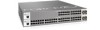
www.dell.com | support.dell.com Figure 5-15. DC-DC Cable for S50N Follow the steps below to connect the switch to the PSU: Step Task 1 With the switch unplugged from AC power, connect the DC-DC plug to the switch. Connect the individual leads of the DC-to-DC cable to the DC terminal lugs of the S50N switch (Figure 5-16) using a #2 Phillips screwdriver. Connect the gray wire to FG (field ground), red to RTN, brown to -48V: Figure 5-16. DC Terminals of the S50N Connected to the PSU Cable 38 | Installing Backup Power
-
 1
1 -
2
-
3
-
4
-
5
-
6
-
7
-
8
-
9
-
10
-
11
-
12
-
13
-
14
-
15
-
16
-
17
-
18
-
19
-
20
-
21
-
22
-
23
-
24
-
25
-
26
-
27
-
28
-
29
-
30
-
31
-
32
-
 33
33 -
 34
34 -
 35
35 -
 36
36 -
 37
37 -
 38
38 -
 39
39 -
 40
40 -
 41
41 -
 42
42 -
 43
43 -
44
-
45
-
46
-
47
-
48
-
49
-
50
-
51
-
52
-
53
-
54
-
55
-
56
-
57
-
58
-
59
-
60
-
61
-
62
-
63
-
64
 |
 |

38
|
Installing Backup Power
www.dell.com | support.dell.com
Figure 5-15.
DC-DC Cable for S50N
Follow the steps below to connect the switch to the PSU:
Step
Task
1
With the switch unplugged from AC power, connect the DC-DC plug to the switch. Connect the individual leads
of the DC-to-DC cable to the DC terminal lugs of the S50N switch (
Figure
5-
16
) using a #2 Phillips screwdriver.
Connect the gray wire to FG (field ground), red to RTN, brown to -48V:
Figure 5-16.
DC Terminals of the S50N Connected to the PSU Cable