Dell Inspiron N5010 Service Manual - Page 17
step 5, step 17, Replacing the System Board, Replacing the Battery, Back to Contents - fan
 |
View all Dell Inspiron N5010 manuals
Add to My Manuals
Save this manual to your list of manuals |
Page 17 highlights
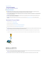
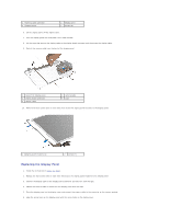
2. Place the processor heat sink on the system board. 3. Align the four captive screws on the processor heat sink with the screw holes on the system board and tighten the screws in sequential order (indicated on the processor heat sink). NOTE: The appearance and number of screws on the processor heat sink may vary based on the your computer model. 4. Connect the fan cable to the connector on the system board. 5. Follow the instructions from step 5 to step 17 in Replacing the System Board. 6. Replace the battery (see Replacing the Battery). CAUTION: Before turning on the computer, replace all screws and ensure that no stray screws remain inside the computer. Failure to do so may result in damage to the computer. Back to Contents Page
-
 1
1 -
2
-
3
-
4
-
5
-
6
-
7
-
8
-
9
-
10
-
11
-
 12
12 -
 13
13 -
 14
14 -
 15
15 -
 16
16 -
 17
17 -
 18
18 -
 19
19 -
 20
20 -
 21
21 -
 22
22 -
23
-
24
-
25
-
26
-
27
-
28
-
29
-
30
-
31
-
32
-
33
-
34
-
35
-
36
-
37
-
38
-
39
-
40
-
41
-
42
-
43
-
44
-
45
-
46
-
47
-
48
-
49
-
50
-
51
 |
 |

2.
Place the processor heat sink on the system board.
3.
Align the four captive screws on the processor heat sink with the screw holes on the system board and tighten the screws in sequential order (indicated
on the processor heat sink).
4.
Connect the fan cable to the connector on the system board.
5.
Follow the instructions from
step 5
to
step 17
in
Replacing the System Board
.
6.
Replace the battery (see
Replacing the Battery
).
Back to Contents Page
NOTE:
The appearance and number of screws on the processor heat sink may vary based on the your computer model.
CAUTION:
Before turning on the computer, replace all screws and ensure that no stray screws remain inside the computer. Failure to do so may
result in damage to the computer.