Dell Inspiron N5010 Service Manual - Page 51
Replacing the VGA Connector Board
 |
View all Dell Inspiron N5010 manuals
Add to My Manuals
Save this manual to your list of manuals |
Page 51 highlights
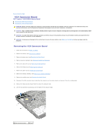
3 system board connector Replacing the VGA Connector Board 1. Follow the instructions in Before You Begin. 2. Place the VGA connector board along with the cable on the computer base and press the VGA connector board until it is seated fully. 3. Route the VGA connector board cable into the routing guide and connect the cable to the connector on the system board. 4. Replace the middle cover (see Replacing the Middle Cover). 5. Replace the display assembly (see Replacing the Display Assembly). 6. Replace the palm rest (see Replacing the Palm Rest). 7. Replace the keyboard (see Replacing the Keyboard). 8. Replace the optical drive (see Replacing the Optical Drive). 9. Replace memory module(s) (see Replacing the Memory Module(s)). 10. Replace the base cover (see Replacing the Base Cover). 11. Replace the battery (see Replacing the Battery). CAUTION: Before turning on the computer, replace all screws and ensure that no stray screws remain inside the computer. Failure to do so may result in damage to the computer. Back to Contents Page
-
 1
1 -
2
-
3
-
4
-
5
-
6
-
7
-
8
-
9
-
10
-
11
-
12
-
13
-
14
-
15
-
16
-
17
-
18
-
19
-
20
-
21
-
22
-
23
-
24
-
25
-
26
-
27
-
28
-
29
-
30
-
31
-
32
-
33
-
34
-
35
-
36
-
37
-
38
-
39
-
40
-
41
-
42
-
43
-
44
-
45
-
 46
46 -
 47
47 -
 48
48 -
 49
49 -
 50
50 -
 51
51
 |
 |