Dell Inspiron N5010 Service Manual - Page 41
Replacing the Palm Rest
 |
View all Dell Inspiron N5010 manuals
Add to My Manuals
Save this manual to your list of manuals |
Page 41 highlights
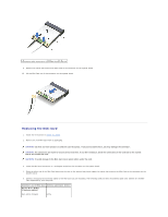
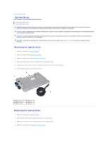
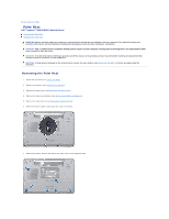
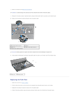
8. Remove the keyboard (see Removing the Keyboard). CAUTION: To avoid damage to the connectors, lift the connector latch and then remove the cables. 9. Disconnect the touch pad cable, status light cable, and power button cable from the connectors on the system board. 10. Remove the five screws that secure the plam rest to the system board. 1 touch pad cable connector 3 palm rest 5 power button cable connector 2 screw 4 status light cable connector CAUTION: Carefully separate the palm rest from the computer base to avoid damage to the palm rest. 11. Slide a plastic scribe between the computer base and the palm rest and pry out the palm rest off the computer base. 1 palm rest 2 plastic scribe Replacing the Palm Rest 1. Follow the instructions in Before You Begin. 2. Slide the tabs on the palm rest into the slots on the computer base and gently snap the palm rest into place. 3. Replace the five screws that secure the plam rest to the system board. 4. Connect the touch pad cable, status light cable, and power button cable to the connectors on the system board.
-
 1
1 -
2
-
3
-
4
-
5
-
6
-
7
-
8
-
9
-
10
-
11
-
12
-
13
-
14
-
15
-
16
-
17
-
18
-
19
-
20
-
21
-
22
-
23
-
24
-
25
-
26
-
27
-
28
-
29
-
30
-
31
-
32
-
33
-
34
-
35
-
 36
36 -
 37
37 -
 38
38 -
 39
39 -
 40
40 -
 41
41 -
 42
42 -
 43
43 -
 44
44 -
 45
45 -
 46
46 -
47
-
48
-
49
-
50
-
51
 |
 |
