Dell Inspiron N5010 Service Manual - Page 21
Replacing the Display Panel
 |
View all Dell Inspiron N5010 manuals
Add to My Manuals
Save this manual to your list of manuals |
Page 21 highlights
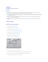
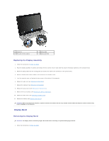
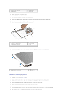
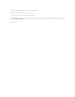
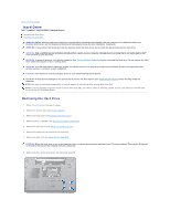
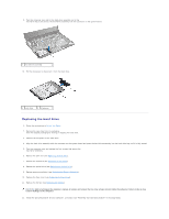
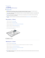
1 camera cable connector 3 display panel 2 display cover 4 screws (8) 6. Lift the display panel off the display cover. 7. Turn the display panel over and place it on a clean surface. 8. Lift the tape that secures the display cable to the display board connector and disconnect the display cable. 9. Peel off the camera cable from the back of the display panel. 1 back of the display panel 3 display board connector 5 display cable 2 camera cable 4 tape 10. Remove the four screws (two on each side) that secure the display panel brackets to the display panel. 1 display panel brackets (2) 2 screws (4) Replacing the Display Panel 1. Follow the instructions in Before You Begin. 2. Replace the four screws (two on each side) that secure the display panel brackets to the display panel. 3. Connect the display cable to the display board connector and secure it with the tape. 4. Adhere the camera cable to the back of the display panel with the tape. 5. Place the display panel on the display cover and connect the camera cable to the connector on the camera module. 6. Align the screw holes on the display panel with the screw holes on the display cover.
-
 1
1 -
2
-
3
-
4
-
5
-
6
-
7
-
8
-
9
-
10
-
11
-
12
-
13
-
14
-
15
-
 16
16 -
 17
17 -
 18
18 -
 19
19 -
 20
20 -
 21
21 -
 22
22 -
 23
23 -
 24
24 -
 25
25 -
 26
26 -
27
-
28
-
29
-
30
-
31
-
32
-
33
-
34
-
35
-
36
-
37
-
38
-
39
-
40
-
41
-
42
-
43
-
44
-
45
-
46
-
47
-
48
-
49
-
50
-
51
 |
 |
