Dell Latitude 7212 Rugged Extreme Tablet Latitude 12 Rugged Extreme Tablet - 7
Dell Latitude 7212 Rugged Extreme Tablet Manual
 |
View all Dell Latitude 7212 Rugged Extreme Tablet manuals
Add to My Manuals
Save this manual to your list of manuals |
Dell Latitude 7212 Rugged Extreme Tablet manual content summary:
- Dell Latitude 7212 Rugged Extreme Tablet | Latitude 12 Rugged Extreme Tablet - 7 - Page 1
Latitude 12 Rugged Extreme Tablet - 7212 Owner's Manual Regulatory Model: T03H Regulatory Type: T03H002 - Dell Latitude 7212 Rugged Extreme Tablet | Latitude 12 Rugged Extreme Tablet - 7 - Page 2
of data and tells you how to avoid the problem. WARNING: A WARNING indicates a potential for property damage, personal injury, or death. © 2018 Dell Inc. or its subsidiaries. All rights reserved. Dell, EMC, and other trademarks are trademarks of Dell Inc. or its subsidiaries. Other trademarks may be - Dell Latitude 7212 Rugged Extreme Tablet | Latitude 12 Rugged Extreme Tablet - 7 - Page 3
battery when the cross strap is attached - Optional 15 Subscriber Identification Module (SIM) card...15 Removing uSIM...15 Inserting the uSIM...16 Display assembly...16 Removing display assembly...16 Installing display assembly...20 Stylus...21 Removing stylus...21 Installing stylus...21 WLAN card - Dell Latitude 7212 Rugged Extreme Tablet | Latitude 12 Rugged Extreme Tablet - 7 - Page 4
system board...46 Docking Board...46 Removing docking board...46 Installing docking board...47 Supported operating systems...60 Downloading drivers...60 Intel audio drivers...61 Intel chipset drivers...61 Intel HD Graphics drivers...61 Network drivers...62 System devices drivers...62 Storage drivers - Dell Latitude 7212 Rugged Extreme Tablet | Latitude 12 Rugged Extreme Tablet - 7 - Page 5
Features...64 Power and battery-status light...65 System Support Assist System Resolution...82 7 Troubleshooting...83 Dell Enhanced Pre-Boot System Assessment - ePSA diagnostic 3.0 83 Diagnostic LED...83 General Troubleshooting...84 8 Ecosystem Accessories...86 Active Stylus...86 Getting the stylus - Dell Latitude 7212 Rugged Extreme Tablet | Latitude 12 Rugged Extreme Tablet - 7 - Page 6
System right view...89 Dock front view...89 Keyboard Dock ...90 Turn the Backlight On - Off and Adjust Brightness 91 Keyboard Function - Fn Key Lock ...91 Dock rear view...92 Input Output module...92 Rugged tablet vehicle dock...93 6 Contents - Dell Latitude 7212 Rugged Extreme Tablet | Latitude 12 Rugged Extreme Tablet - 7 - Page 7
only perform troubleshooting and simple repairs as authorized in your product documentation, or as directed by the online or telephone service and support team. Damage due to servicing that is not authorized by Dell is not covered by your warranty. Read and follow the safety instructions that came - Dell Latitude 7212 Rugged Extreme Tablet | Latitude 12 Rugged Extreme Tablet - 7 - Page 8
NOTE: Open the display if the system is a laptop. 10 Press the power button to ground the system battery designed for this particular Dell computer. Do not use batteries designed for other Dell computers. 1 Connect any external devices, such as a port replicator or media base, and replace any cards - Dell Latitude 7212 Rugged Extreme Tablet | Latitude 12 Rugged Extreme Tablet - 7 - Page 9
: • Phillips #0 screwdriver • Phillips #1 screwdriver • Standard DSP plastic scribe Screw size list Table 1. Latitude 7212 Rugged Extreme Tablet screw size list Component M2*2 M2*2.5 M2*3 Smart card 6 Bottom Base 6 81 Front Camera Rear Camera Protective Rubber Bumper( all four corners - Dell Latitude 7212 Rugged Extreme Tablet | Latitude 12 Rugged Extreme Tablet - 7 - Page 10
of fire or explosion. Replace the battery only with a compatible battery purchased from Dell. The battery is designed to work with your Dell Tablet. Do not use a battery from any other computer with your tablet. WARNING: Before removing or replacing the battery, turn off the computer, disconnect the - Dell Latitude 7212 Rugged Extreme Tablet | Latitude 12 Rugged Extreme Tablet - 7 - Page 11
The battery is released from the battery bay. 4 Lift the edge of the battery that pops up. Removing and installing components 11 - Dell Latitude 7212 Rugged Extreme Tablet | Latitude 12 Rugged Extreme Tablet - 7 - Page 12
of fire or explosion. Replace the battery only with a compatible battery purchased from Dell. The battery is designed to work with your Dell Tablet. Do not use a battery from any other computer with your tablet. WARNING: Before removing or replacing the battery, turn off the computer, disconnect the - Dell Latitude 7212 Rugged Extreme Tablet | Latitude 12 Rugged Extreme Tablet - 7 - Page 13
3 Slide the strap and release the strap from the holder to access the battery latch. 4 Slide the battery latch to unlock the battery release latch and then push the latch in a downward direction to release the battery. Removing and installing components 13 - Dell Latitude 7212 Rugged Extreme Tablet | Latitude 12 Rugged Extreme Tablet - 7 - Page 14
into the slot until it clicks into place. 3 Make sure the battery latch is back to the locked state. NOTE: There are two battery. Perform steps 1 to 3 to install battery 1 and battery 2 on the tablet. 4 Follow the procedure in After working inside your computer. 14 Removing and installing components - Dell Latitude 7212 Rugged Extreme Tablet | Latitude 12 Rugged Extreme Tablet - 7 - Page 15
in After working inside your computer. Subscriber Identification Module (SIM) card Removing uSIM 1 Follow the procedure in Before working inside your computer. 2 Remove the left battery. 3 Lift the latch [1] and pull the SIM slot cap [2]. 4 Pull the SIM from the slot until it is released [3]. NOTE - Dell Latitude 7212 Rugged Extreme Tablet | Latitude 12 Rugged Extreme Tablet - 7 - Page 16
Ensure the gold chip is facing down in the slot. c Press the SIM slot cap to initial state. 3 Follow the procedure in After working 1 Follow the procedure in Before working inside your computer. 2 Remove the: a Battery 3 To remove the display assembly (with plastic scribe): a Place the display side - Dell Latitude 7212 Rugged Extreme Tablet | Latitude 12 Rugged Extreme Tablet - 7 - Page 17
plastic scribe should be inserted to avoid damage to the seal on the LCD and to the clips that secure the LCD display to the tablet chassis. 6 Pry the edges starting from Windows button clockwise [1,2]. NOTE: Gently pry the edges evenly to unlock the plastic clips that secures the display assembly - Dell Latitude 7212 Rugged Extreme Tablet | Latitude 12 Rugged Extreme Tablet - 7 - Page 18
7 Lift the display assembly [1] by angle 15° and slide it from the chassis [2]. 8 Flip the display assembly by an angle less than 90°. NOTE: Ensure not to flip more than 90° angle, as the display assembly ports and cables are connected to the system board and may damage the display cables. 9 Before - Dell Latitude 7212 Rugged Extreme Tablet | Latitude 12 Rugged Extreme Tablet - 7 - Page 19
b Flip open the display panel to 90° angle and lay it angled on the tablet chassis. 10 To disconnect the display cable: a Remove the adhesive tape that secures the LVDS cable display cable from the display panel. 11 Remove the display assembly from the tablet. Removing and installing components 19 - Dell Latitude 7212 Rugged Extreme Tablet | Latitude 12 Rugged Extreme Tablet - 7 - Page 20
a support to attain tablet chassis and press the edges to snap-in. NOTE: • Ensure that the Window button on the display assembly aligns with the docking battery is at top view. NOTE: Ensure to place the system in a flat surface. 9 Replace the screws (19) to secure the display assembly to the tablet - Dell Latitude 7212 Rugged Extreme Tablet | Latitude 12 Rugged Extreme Tablet - 7 - Page 21
is ready to assist you in using the rugged tablet. For more details, see Getting the stylus ready for use Installing stylus 1 Align the stylus with the groove on the tablet. 2 Push and smoothly slide it inside to secure the stylus. NOTE: Avoid hanging the stylus detached from its groove when not in - Dell Latitude 7212 Rugged Extreme Tablet | Latitude 12 Rugged Extreme Tablet - 7 - Page 22
1 Follow the procedure in Before working inside your computer. 2 Remove the: a Battery b Display assembly 3 To remove the WLAN card: a Place the back side of system on a flat surface. b Locate the WLAN card. c Remove the screw that secures the WLAN bracket to the system board [1]. d Lift the metal - Dell Latitude 7212 Rugged Extreme Tablet | Latitude 12 Rugged Extreme Tablet - 7 - Page 23
1 Follow the procedure in Before working inside your computer. 2 Remove the: a Battery b Display assembly 3 To remove the WWAN card: a Place the back side of system on a flat surface. b Locate the WWAN card. c Remove the screw that secures the WWAN bracket to the system board [1]. d Lift the metal - Dell Latitude 7212 Rugged Extreme Tablet | Latitude 12 Rugged Extreme Tablet - 7 - Page 24
Connect the WWAN cables to the connectors on the WWAN card. NOTE: The IMEI number is visible on the WWAN card. 3 To secure the WWAN card, place the metal bracket and tighten the M2.0 x 3.0 screw. 4 Install the: a Display assembly b Battery 5 Follow the procedure in After working inside your computer - Dell Latitude 7212 Rugged Extreme Tablet | Latitude 12 Rugged Extreme Tablet - 7 - Page 25
when checksum error is displayed in booting. Installing CMOS battery 1 Align the CMOS battery over the rubber pad on top of the fingerprint reader. 2 Press the CMOS battery on the adhesive tape. NOTE: CMOS battery for the tablet is insulated in a protective shield. To avoid poor connection of - Dell Latitude 7212 Rugged Extreme Tablet | Latitude 12 Rugged Extreme Tablet - 7 - Page 26
inside your computer. Power button assembly Removing power button assembly 1 Follow the procedure in Before working inside your computer. 2 Remove the: a Battery b Display assembly 3 To remove the power button assembly: a Place the back side of system on a flat surface. b Locate the power button - Dell Latitude 7212 Rugged Extreme Tablet | Latitude 12 Rugged Extreme Tablet - 7 - Page 27
the power button cable is routed between the square gap in the power button bracket. 2 Push the power button assembly in the slot on the tablet chassis. NOTE: Ensure NOT to insert the power button from the exterior right view. 3 Secure the power button assembly with the adhesive tape. 4 Replace the - Dell Latitude 7212 Rugged Extreme Tablet | Latitude 12 Rugged Extreme Tablet - 7 - Page 28
power connector port Removing micro serial port and power connector port 1 Follow the procedure in Before working inside your computer. 2 Remove the: a Battery b Display assembly 3 To remove the micro serial port and power connector port: a Place the back side of system on a flat surface. b Locate - Dell Latitude 7212 Rugged Extreme Tablet | Latitude 12 Rugged Extreme Tablet - 7 - Page 29
Removing and installing components 29 - Dell Latitude 7212 Rugged Extreme Tablet | Latitude 12 Rugged Extreme Tablet - 7 - Page 30
are assembled as one single component to connect on the tablet system board. NOTE: Malfunction of either component requires to the screw (1) to the system board. 8 Install the: a Display assembly b Battery 9 Follow the procedure in After working inside your computer. Front camera Removing front - Dell Latitude 7212 Rugged Extreme Tablet | Latitude 12 Rugged Extreme Tablet - 7 - Page 31
b Locate the front camera. c Slide the camera shutter towards right, to bring the lens cover is in the open position [1]. d Insert the edge of the plastic scribe between the gap of lens shutter and lift camera lens shutter [2]. e Remove the screws (2) that secure the camera on the system chassis - Dell Latitude 7212 Rugged Extreme Tablet | Latitude 12 Rugged Extreme Tablet - 7 - Page 32
g Flip the camera circuit board with a plastic scribe [1]. h Disconnect the camera cable that secures the cable to the system board [2]. 32 Removing and installing components - Dell Latitude 7212 Rugged Extreme Tablet | Latitude 12 Rugged Extreme Tablet - 7 - Page 33
the front camera circuit board on the system board. 6 Slide the lens shutter in the lens channel and push towards left. 7 Install the: a Display assembly b Battery 8 Follow the procedure in After working inside your computer. Removing and installing components 33 - Dell Latitude 7212 Rugged Extreme Tablet | Latitude 12 Rugged Extreme Tablet - 7 - Page 34
microphone 1 Follow the procedure in Before working inside your computer. 2 Remove the: a Battery b Display assembly 3 To remove the microphone: a Place the back side of system on the microphone assembly and, lift the microphone form the tablet chassis [3]. 34 Removing and installing components - Dell Latitude 7212 Rugged Extreme Tablet | Latitude 12 Rugged Extreme Tablet - 7 - Page 35
input and replace the screw (1) in the bracket to secure the microphone to the tablet chassis. 4 Align the microphone IC board on the chassis and replace the screw Install the: a Display assembly b Battery 7 Follow the procedure in After working inside your computer. Removing and installing components - Dell Latitude 7212 Rugged Extreme Tablet | Latitude 12 Rugged Extreme Tablet - 7 - Page 36
PCIE 1 Follow the procedure in Before working inside your computer. 2 Remove the: a Battery b Display assembly 3 To remove the heatsink: a Place the back side of system in malfunction and over heating of the tablet. Installing heatsink for SSD or PCIE 1 Align the heatsink on the system - Dell Latitude 7212 Rugged Extreme Tablet | Latitude 12 Rugged Extreme Tablet - 7 - Page 37
screws (4) to secure the heatsink to the tablet chassis. 3 Install the: a Display assembly b Battery 4 Follow the procedure in After working inside board [1]. d Slide and lift the SSD card from the connector on the system board [2]. NOTE: Ensure to lift the SSD card by an angle NOT more than 30°. - Dell Latitude 7212 Rugged Extreme Tablet | Latitude 12 Rugged Extreme Tablet - 7 - Page 38
CAUTION: Lift the SSD card by the side. DO NOT touch the circuit. Installing PCIe 35°. 2 Replace the screw (1) to secure the SSD module to the tablet chassis. 3 Install the: a Heat sink b Display assembly c Battery 4 Follow the procedure in After working inside your computer. System fan Removing - Dell Latitude 7212 Rugged Extreme Tablet | Latitude 12 Rugged Extreme Tablet - 7 - Page 39
the routing channel. 3 Replace the screws (4) to secure the system fan to the tablet chassis. 4 Connect the system fan cable to the system board. 5 Install the: a Heat sink b Display assembly c Battery 6 Follow the procedure in After working inside your computer. Removing and installing components - Dell Latitude 7212 Rugged Extreme Tablet | Latitude 12 Rugged Extreme Tablet - 7 - Page 40
System Board Removing system board 1 Follow the procedure in Before working inside your computer. 2 Remove the: a Battery b Micro SIM c Display assembly d Heat sink e SSD f System fan g WLAN h WWAN 3 Perform the following before removing the system board: a Place the back side of system on a flat - Dell Latitude 7212 Rugged Extreme Tablet | Latitude 12 Rugged Extreme Tablet - 7 - Page 41
cable with a plastic scribe on the system board [2]. h Remove the adhesive tape that insulates the micro SD card reader cable [3]. i Lift the latch, and slide to remove the micro SD card reader cable [4]. j Lift the latch, and remove the micro serial port cable from the connector [5]. k Removing - Dell Latitude 7212 Rugged Extreme Tablet | Latitude 12 Rugged Extreme Tablet - 7 - Page 42
the microphone latch, and remove the cable [1]. m Disconnect the smart card reader latch, and remove the cable [2]. n Disconnect the cable r Release and gently pull the NFC contactless smart card and smart card cable through the narrow slit in the rubber gasket [8]. 42 Removing and - Dell Latitude 7212 Rugged Extreme Tablet | Latitude 12 Rugged Extreme Tablet - 7 - Page 43
: Push on the connector pin head evenly to securely remove the battery cable. w Disconnect the battery 2 cable from the connector [6]. x Lift the latch with a plastic scribe, and remove the pogo pin docking cable [7]. y Disconnect the speaker cable with a plastic scribe [8]. Removing and installing - Dell Latitude 7212 Rugged Extreme Tablet | Latitude 12 Rugged Extreme Tablet - 7 - Page 44
CAUTION: Speaker cable is accessible after you remove the pogo pin docking connector cable. Ensure to remove pogo pin docking cable before removing speaker cable. 4 To remove the system board: a Remove the screw (1) that connects the antennas for radio pass-through connectors on the system - Dell Latitude 7212 Rugged Extreme Tablet | Latitude 12 Rugged Extreme Tablet - 7 - Page 45
f Remove the screw (7) that secures the system board to the tablet chassis [1]. g Insert the plastic scribe near the system fan screw slot, and slide to release and lift the system board from the tablet chassis [2]. Removing and installing components 45 - Dell Latitude 7212 Rugged Extreme Tablet | Latitude 12 Rugged Extreme Tablet - 7 - Page 46
the screw holes on the tablet chassis. 2 Replace the screws (7) to secure the system board to the tablet chassis. 3 Connect the cables Display assembly f SSD g Battery h Micro SIM 5 Follow the procedure in After working inside your computer. Docking Board Removing docking board 1 Follow the procedure - Dell Latitude 7212 Rugged Extreme Tablet | Latitude 12 Rugged Extreme Tablet - 7 - Page 47
assembly when troubleshooting issues not resolved by replacing the FRU-CRU components. Installing docking board 1 Connect the docking board cable 2 Align the docking board with the screw holes on the tablet chassis. 3 Replace the screws (4) to secure the back docking board to the tablet chassis. 4 - Dell Latitude 7212 Rugged Extreme Tablet | Latitude 12 Rugged Extreme Tablet - 7 - Page 48
: Connect the cables to respective slot that were disconnected while removing the docking board. See removing system board. 5 Install the: a System board b WWAN c WLAN d System fan e Heat sink f Display assembly g Battery 6 Follow the procedure in After working inside your computer. Back Camera - Dell Latitude 7212 Rugged Extreme Tablet | Latitude 12 Rugged Extreme Tablet - 7 - Page 49
b Remove the screws (3) that secures the back camera circuit board on the system board chassis [2]. NOTE: Finger print reader cable head is disconnected from the system board. c Lift the latch, and slide to remove the back camera board cable on the system board [3]. Removing and installing - Dell Latitude 7212 Rugged Extreme Tablet | Latitude 12 Rugged Extreme Tablet - 7 - Page 50
troubleshooting issues are not resolved by replacing the FRU-CRU components. Installing back camera 1 Connect the back camera cable to the connector. 2 Align the back camera circuit board with the screw holes on the tablet f Display assembly g Battery 6 Follow the procedure in After - Dell Latitude 7212 Rugged Extreme Tablet | Latitude 12 Rugged Extreme Tablet - 7 - Page 51
Smartcard holder Removing smartcard holder 1 Follow the procedure in Before working inside your computer. 2 Remove the: a Battery b Display assembly c System board 3 To remove the smartcard holder: a Place the back side of system on a flat surface. b Locate the smartcard holder. c Remove the screws - Dell Latitude 7212 Rugged Extreme Tablet | Latitude 12 Rugged Extreme Tablet - 7 - Page 52
5 Lift the smartcard from the tablet chassis. 52 Removing and installing components - Dell Latitude 7212 Rugged Extreme Tablet | Latitude 12 Rugged Extreme Tablet - 7 - Page 53
smartcard holder 1 Align the smartcard holder in the tablet chassis. 2 Align and press the copper shield to secure the smart card holder. 3 Replace the screws (10) to secure the smartcard. 4 Install the: a Display assembly b System board c Battery 5 Follow the procedure in After working inside your - Dell Latitude 7212 Rugged Extreme Tablet | Latitude 12 Rugged Extreme Tablet - 7 - Page 54
Main Ground Plate • Antenna Right Ground Plate • Antenna WLAN Aux • Antenna WLAN Main • Bottom Casing Assembly • Bumper Brackets • Conductive Dock • Conductive Dock FPC Cable • DC-In Cable • DC-In Door • Fingerprint Reader Bracket • Fingerprint Reader cable • Fingerprint Sensor Module • I/O Door - Dell Latitude 7212 Rugged Extreme Tablet | Latitude 12 Rugged Extreme Tablet - 7 - Page 55
Cable • SIM Card Door • Smart Card Daughterboard (include cable) • Speakers (Left and Right) • Strapcover (Left and Right) • Stylus Tube Assembly the screw holes on the tablet chassis. 3 Replace the screws (3) to secure the back camera circuit board to the tablet chassis. 4 Connect the finger - Dell Latitude 7212 Rugged Extreme Tablet | Latitude 12 Rugged Extreme Tablet - 7 - Page 56
g Battery 6 Follow the procedure in After working inside your computer. 56 Removing and installing components - Dell Latitude 7212 Rugged Extreme Tablet | Latitude 12 Rugged Extreme Tablet - 7 - Page 57
This laptop is shipped with power adapter. WARNING: When you disconnect the power adapter cable from the laptop, computer and peripheral devices such as mice and keyboards, external hard drive or optical devices, Bluetooth transfers and support for new transfer types • Backward USB - Dell Latitude 7212 Rugged Extreme Tablet | Latitude 12 Rugged Extreme Tablet - 7 - Page 58
• New connectors and cable The topics below cover some of the most commonly asked questions regarding USB 3.0/USB 3.1 Gen 1. Speed Currently, there are 3 speed modes defined by the latest USB 3.0/USB 3.1 Gen 1 specification. They are Super-Speed, Hi-Speed and FullSpeed. The new SuperSpeed mode has a - Dell Latitude 7212 Rugged Extreme Tablet | Latitude 12 Rugged Extreme Tablet - 7 - Page 59
USB 3.0/USB 3.1 Gen 1 Drive Docks & Adapters • USB 3.0/USB 3.1 Gen 3.1 Gen 1 Adapter Cards & Hubs Compatibility The drivers for USB 3.0/USB 3.1 Gen 1 controllers. Microsoft announced that Windows 7 would have USB 3.1 Gen 1 support, perhaps not on its immediate release, but in a subsequent Service - Dell Latitude 7212 Rugged Extreme Tablet | Latitude 12 Rugged Extreme Tablet - 7 - Page 60
Downloading drivers 1 Turn on the laptop. 2 Go to Dell.com/support. 3 Click Product Support, enter the Service Tag of your laptop, and then click Submit. NOTE: If you do not have the Service Tag, use the auto detect feature or manually browse for your laptop model. 4 Click Drivers and Downloads - Dell Latitude 7212 Rugged Extreme Tablet | Latitude 12 Rugged Extreme Tablet - 7 - Page 61
are already installed in the laptop. Table 5. Intel chipset drivers Before installation After installation Intel HD Graphics drivers Verify if the Intel HD Graphics drivers are already installed in the laptop. Table 6. Intel HD Graphics drivers Before installation After installation Software - Dell Latitude 7212 Rugged Extreme Tablet | Latitude 12 Rugged Extreme Tablet - 7 - Page 62
if the Network drivers are already installed in the laptop. Table 7. Network drivers Before installation After installation System devices drivers Verify if the System devices drivers are already installed in the laptop. Table 8. System devices drivers Before installation After installation - Dell Latitude 7212 Rugged Extreme Tablet | Latitude 12 Rugged Extreme Tablet - 7 - Page 63
Storage drivers Verify if the Storage drivers are already installed in the laptop. Table 9. Storage drivers Before installation After installation Software 63 - Dell Latitude 7212 Rugged Extreme Tablet | Latitude 12 Rugged Extreme Tablet - 7 - Page 64
of the Latitude 7212 Rugged Extreme Tablet include the following: • Outdoor viewable and capacitive Glovetouch touch screen • Dual hot-swap battery • Enhanced 4th-generation quad-cool thermal management that allows the tablet to operate in extreme temperatures • Designed with Dell Rugged universal - Dell Latitude 7212 Rugged Extreme Tablet | Latitude 12 Rugged Extreme Tablet - 7 - Page 65
details the power and status light of the tablet. Indicates the power state and battery state of the computer. • Solid green-Power adapter is connected and the battery is charging. • Solid amber-Battery charge is low or critical. • Off-Battery is fully charged. System specifications Feature Chipset - Dell Latitude 7212 Rugged Extreme Tablet | Latitude 12 Rugged Extreme Tablet - 7 - Page 66
Integrated video • On system - eDP (internal display) • Optional Type-C port - VGA, DisplayPort 1.2, DVI NOTE: Supports one VGA, DisplayPort, HDMI through the Docking station. Camera specifications Feature Type Sensor type Imaging rate Video Resolution Specification • Front Camera - 5 MP fixed - Dell Latitude 7212 Rugged Extreme Tablet | Latitude 12 Rugged Extreme Tablet - 7 - Page 67
1x micro serial connector • One Docking Port • One Dual (WLAN/WWAN) RF passthrough USB ports • One USB 3.1 Gen 1 port with PowerShare • One displayPort with PowerShare over USB Type-C Memory card reader One microSD card reader SIM card slot One micro-SIM slot with security feature Modular - Dell Latitude 7212 Rugged Extreme Tablet | Latitude 12 Rugged Extreme Tablet - 7 - Page 68
Feature Operating angle Minimum viewing angles (horizontal) Specification 0° (closed) to 180° • 89 TYP Minimum viewing angles (vertical) • 89 TYP Pixel pitch 0.1335 mm Touch specifications Feature Sample report Rate Response Latency Touch accuracy Specification >= 100 Hz per finger/pen - Dell Latitude 7212 Rugged Extreme Tablet | Latitude 12 Rugged Extreme Tablet - 7 - Page 69
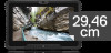
) 24.40 mm (0.96 inches) 28.90 mm (1.14 inches) Weight Maximum: 1.27 kg (2.82 lbs) NOTE: The weight of the tablet will vary depending on the configuration ordered and the manufacturing variability. Environmental specifications Feature Specifications Temperature - operating -29°C to 63°C (20 - Dell Latitude 7212 Rugged Extreme Tablet | Latitude 12 Rugged Extreme Tablet - 7 - Page 70
boot device order and boot directly to a specific device (for example: optical drive or hard drive). During the Power-on Self Test (POST), when the Dell logo appears, you can: • Access System Setup by pressing F2 key • Bring up the one-time boot menu by pressing F12 key The one-time - Dell Latitude 7212 Rugged Extreme Tablet | Latitude 12 Rugged Extreme Tablet - 7 - Page 71
Service Tag, Asset Tag, Ownership Tag, Ownership Date, Manufacture Date, and the Express Service Primary Hard Drive, MiniCard Device, ODD Device, Dock eSATA Device, LOM MAC Address, Video Controller, Cellular Device, Bluetooth Device. Battery Information Displays the battery status and the type of - Dell Latitude 7212 Rugged Extreme Tablet | Latitude 12 Rugged Extreme Tablet - 7 - Page 72
cannot see any device attached to this port. The options are: • Enable USB Boot Support This option is enabled by default. • Enable External USB Ports This option is enabled by default. NOTE: The USB keyboard and mouse always work in the BIOS setup irrespective of these settings. USB PowerShare - Dell Latitude 7212 Rugged Extreme Tablet | Latitude 12 Rugged Extreme Tablet - 7 - Page 73
30 seconds • 1 minute • 5 minute • 15 minute • Never Keyboard Backlight The Keyboard Backlight with Battery option does not affect the main keyboard illumination feature. Keyboard Timeout on Battery Illumination continues to support the various illumination levels. The options are: • 5 seconds • 10 - Dell Latitude 7212 Rugged Extreme Tablet | Latitude 12 Rugged Extreme Tablet - 7 - Page 74
This option is enabled by default. You can configure the various devices of the tablet. The options are: • Enable User-Facing Camera. This option is enabled by on the power source (On Battery and On AC). NOTE: The video setting will be visible only when a video card is installed into the system. - Dell Latitude 7212 Rugged Extreme Tablet | Latitude 12 Rugged Extreme Tablet - 7 - Page 75
Computrace (R) Allows you to activate or disable the optional Computrace Service from Absolute software. The options are: • Deactivate • Disable • feature and no further changes will be allowed Default setting: Activate OROM Keyboard Access Allows you to set an option to enter the Option ROM - Dell Latitude 7212 Rugged Extreme Tablet | Latitude 12 Rugged Extreme Tablet - 7 - Page 76
Option Admin Setup Lockout Description Allows you to prevent users from entering the setup when an Administrator password is set. Enable Admin Setup Lockout This option is not selected by default. Master Password Lockout Allows you to prevent users from entering the setup when an Master password - Dell Latitude 7212 Rugged Extreme Tablet | Latitude 12 Rugged Extreme Tablet - 7 - Page 77
improves with the additional cores. This option is enabled by default. Allows you to enable or disable multi-core support for the processor. • Enable Multi Core Support Default setting: The option is enabled. Intel SpeedStep Allows you to enable or disable the Intel SpeedStep mode of - Dell Latitude 7212 Rugged Extreme Tablet | Latitude 12 Rugged Extreme Tablet - 7 - Page 78
from all the USB ports to conserve battery power. The option is: • Enable USB Wake Support This option is disabled by default. battery at a standard rate. • ExpressCharge - The battery charges over a shorter period of time using Dell's fast charging technology. • Primarily AC use Extends the battery - Dell Latitude 7212 Rugged Extreme Tablet | Latitude 12 Rugged Extreme Tablet - 7 - Page 79
batteries. To enable this option, disable the Advanced Battery Charge Configuration option. Dock Battery Charger Mode You can choose the charging mode for the battery of two methods to enable the keypad that is embedded in the internal keyboard. • Fn Key Only This option is enabled by default. • By - Dell Latitude 7212 Rugged Extreme Tablet | Latitude 12 Rugged Extreme Tablet - 7 - Page 80
power button is pressed to turn on the system. The options are: • Enable Tablet Button LED Sign of Life This option is selected by default. Warnings and Errors - Allows you to replace the external NIC MAC address in a supported dock or dongle with the selected MAC address Through from the system. - Dell Latitude 7212 Rugged Extreme Tablet | Latitude 12 Rugged Extreme Tablet - 7 - Page 81
devices. The options are: • WWAN/GPS • WLAN/WiGig • Bluetooth NOTE: These options are enabled by default. Maintenance Option Service Tag Asset Tag BIOS Downgrade Description Displays the Service Tag of your computer. Allows you to create a system asset tag if an asset tag is not already set. This - Dell Latitude 7212 Rugged Extreme Tablet | Latitude 12 Rugged Extreme Tablet - 7 - Page 82
Assist System Resolution Option Auto OS Recovery Threshold Description Allows you to control the automatic boot flow for Support Assist System Resolution Console and for OS Recovery Tool. The options are: • OFF •1 • 2 This option is enabled by default. •3 SupportAssist OS Recovery Allows - Dell Latitude 7212 Rugged Extreme Tablet | Latitude 12 Rugged Extreme Tablet - 7 - Page 83
7 Troubleshooting Dell Enhanced Pre-Boot System Assessment - ePSA diagnostic 3.0 You can invoke the BIOS and ePSA diagnostics by either: NOTE: As the rugged tablet is without keyboard, perform the following ePSA diagnostic. • To enter BIOS (system setup) without keyboard, Power on system. Press on - Dell Latitude 7212 Rugged Extreme Tablet | Latitude 12 Rugged Extreme Tablet - 7 - Page 84
tablet, the problems may be related to BIOS settings configured incorrectly in BIOS/System Setup. Check the System Setup pages to verify the settings on each page. Try resetting BIOS to default settings by pressing Alt+F. Touchpad and Keyboard To troubleshoot touchpad and keyboard-related problems - Dell Latitude 7212 Rugged Extreme Tablet | Latitude 12 Rugged Extreme Tablet - 7 - Page 85
VGA functionality. When troubleshooting an external monitor, keep these tips in mind: • Check both ends of the cable for a snug connection into the laptop and into the external monitor. • Adjust the contrast and brightness controls on the external monitor. • Make sure that the tablet is not set to - Dell Latitude 7212 Rugged Extreme Tablet | Latitude 12 Rugged Extreme Tablet - 7 - Page 86
• Dock front view • Keyboard Dock • Dock rear view • Input Output module • Rugged tablet vehicle dock Active Stylus This section provides information about the features available on the active stylus. 1 Pen lead provides the finger touch functionality. 3 Middle barrel provides access to the battery - Dell Latitude 7212 Rugged Extreme Tablet | Latitude 12 Rugged Extreme Tablet - 7 - Page 87
battery with the positive side facing the tip of the pen. 3 Reassemble the barrel securely. Setting the Stylus Mode 1 Click on start to launch the ModeSwitch. 2 Select the required mode. 1. Finger ( + Passive Stylus) 2. Active Pen (+ Finger & Passive Stylus) 3. Glove 4. Water Ecosystem Accessories - Dell Latitude 7212 Rugged Extreme Tablet | Latitude 12 Rugged Extreme Tablet - 7 - Page 88
System base view This section contains information on the desk dock. 88 Ecosystem Accessories - Dell Latitude 7212 Rugged Extreme Tablet | Latitude 12 Rugged Extreme Tablet - 7 - Page 89
System right view 1 Microphone 3 Security cable slot Dock front view 2 Quad Cool vent output 1 Tablet Back Support 3 Pogo-pin docking connector 5 USB 2.0 port 2 Alignment pins 4 Power indicator 6 Headset jack Ecosystem Accessories 89 - Dell Latitude 7212 Rugged Extreme Tablet | Latitude 12 Rugged Extreme Tablet - 7 - Page 90
65 indicates that the rugged keyboard is enhanced with protection against dust and low-pressure water jets. To understand more on IP ratings, please refer to the Essential Knowledge page. Backlit Keyboard The keyboard dock comes equipped with a customizable backlit keyboard. The backlight can be - Dell Latitude 7212 Rugged Extreme Tablet | Latitude 12 Rugged Extreme Tablet - 7 - Page 91
the key combination to either adjust the brightness or completely turn off the backlight. Keyboard Function - Fn Key Lock The keyboard has Function key (Fn) lock capability. When activated, the secondary functions on This will return the function keys to the default state. Ecosystem Accessories 91 - Dell Latitude 7212 Rugged Extreme Tablet | Latitude 12 Rugged Extreme Tablet - 7 - Page 92
Spare Battery Charging Slots 3 DC-in jack 5 VGA port 7 2x USB 3.0 port Input Output module 2 Lock slot ( positioned on left side of dock) 4 2x Serial port 6 Display port 8 Gigabit Ethernet The extended Input Output (I/O) Module adds two USB 3.1 ports and an Ethernet port to your Rugged Tablet. The - Dell Latitude 7212 Rugged Extreme Tablet | Latitude 12 Rugged Extreme Tablet - 7 - Page 93
Rugged tablet vehicle dock This section contains information about the Rugged Vehicle Dock. The Rugged Tablet Vehicle Dock is a unique docking solution specially designed for the Latitude 7212 Rugged Extreme Tablet. The dock mounts the tablet in optimal position for vehicle use. It is crash-tested
-
 1
1 -
 2
2 -
 3
3 -
 4
4 -
 5
5 -
 6
6 -
 7
7 -
8
-
9
-
10
-
11
-
12
-
13
-
14
-
15
-
16
-
17
-
18
-
19
-
20
-
21
-
22
-
23
-
24
-
25
-
26
-
27
-
28
-
29
-
30
-
31
-
32
-
33
-
34
-
35
-
36
-
37
-
38
-
39
-
40
-
41
-
42
-
43
-
44
-
45
-
46
-
47
-
48
-
49
-
50
-
51
-
52
-
53
-
54
-
55
-
56
-
57
-
58
-
59
-
60
-
61
-
62
-
63
-
64
-
65
-
66
-
67
-
68
-
69
-
70
-
71
-
72
-
73
-
74
-
75
-
76
-
77
-
78
-
79
-
80
-
81
-
82
-
83
-
84
-
85
-
86
-
87
-
88
-
89
-
90
-
91
-
92
-
93
 |
 |

Latitude 12 Rugged Extreme Tablet – 7212
Owner's Manual
Regulatory Model: T03H
Regulatory Type: T03H002