Dell OptiPlex 9010 AIO Owner's Manual - Page 17
Removing the Intrusion Switch
 |
View all Dell OptiPlex 9010 AIO manuals
Add to My Manuals
Save this manual to your list of manuals |
Page 17 highlights
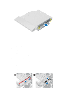
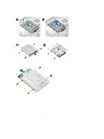
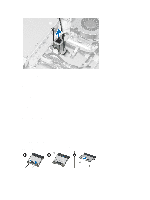
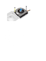
a) VESA mount bracket b) back cover c) VESA stand 6. Follow the procedures in After Working Inside Your Computer. Removing the Intrusion Switch 1. Follow the procedures in Before Working Inside Your Computer. 2. Remove the: a) VESA stand b) back cover c) VESA mount bracket d) system-board shield 3. Disconnect the intrusion cable from the connector on the system board. Unthread the cable from the notches on the computer. 4. Remove the screws that secure the intrusion switch to the chassis. Lift the intrusion switch and remove it from the computer. 17
-
 1
1 -
2
-
3
-
4
-
5
-
6
-
7
-
8
-
9
-
10
-
11
-
 12
12 -
 13
13 -
 14
14 -
 15
15 -
 16
16 -
 17
17 -
 18
18 -
 19
19 -
 20
20 -
 21
21 -
 22
22 -
23
-
24
-
25
-
26
-
27
-
28
-
29
-
30
-
31
-
32
-
33
-
34
-
35
-
36
-
37
-
38
-
39
-
40
-
41
-
42
-
43
-
44
-
45
-
46
-
47
-
48
-
49
-
50
-
51
-
52
-
53
-
54
-
55
-
56
-
57
-
58
-
59
 |
 |
a)
VESA mount bracket
b)
back cover
c)
VESA stand
6.
Follow the procedures in
After Working Inside Your Computer
.
Removing the Intrusion Switch
1.
Follow the procedures in
Before Working Inside Your Computer
.
2.
Remove the:
a)
VESA stand
b)
back cover
c)
VESA mount bracket
d)
system-board shield
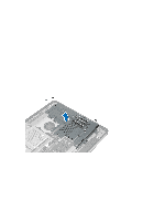
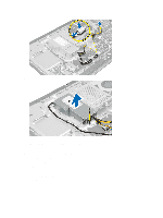
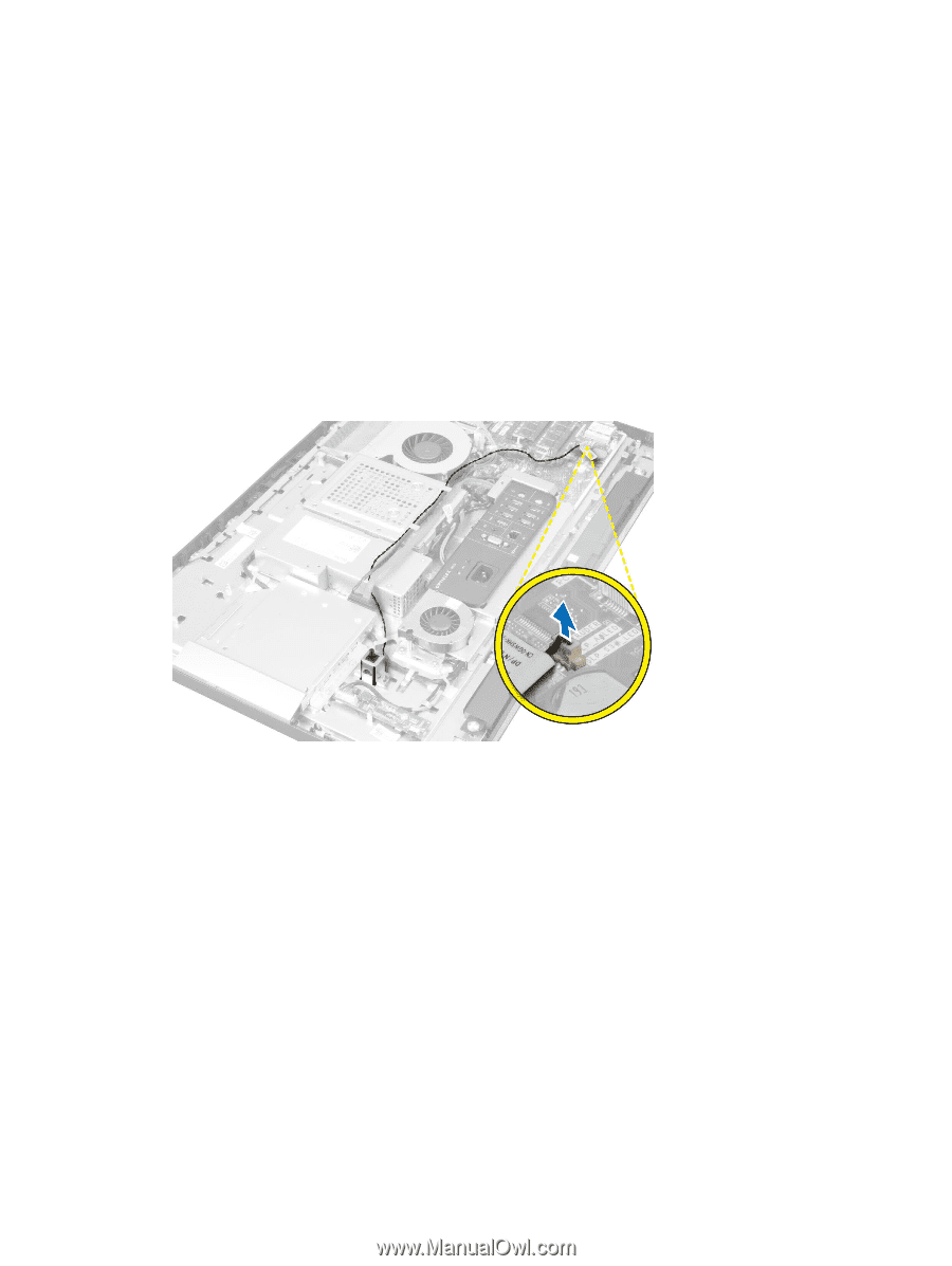
3.
Disconnect the intrusion cable from the connector on the system board. Unthread the cable from the notches on
the computer.
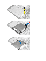
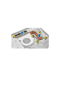
4.
Remove the screws that secure the intrusion switch to the chassis. Lift the intrusion switch and remove it from the
computer.
17