Dell OptiPlex GL Service Manual - Page 13
Dual-Processor Capability, Advanced Expansion Subsystem,
 |
View all Dell OptiPlex GL manuals
Add to My Manuals
Save this manual to your list of manuals |
Page 13 highlights
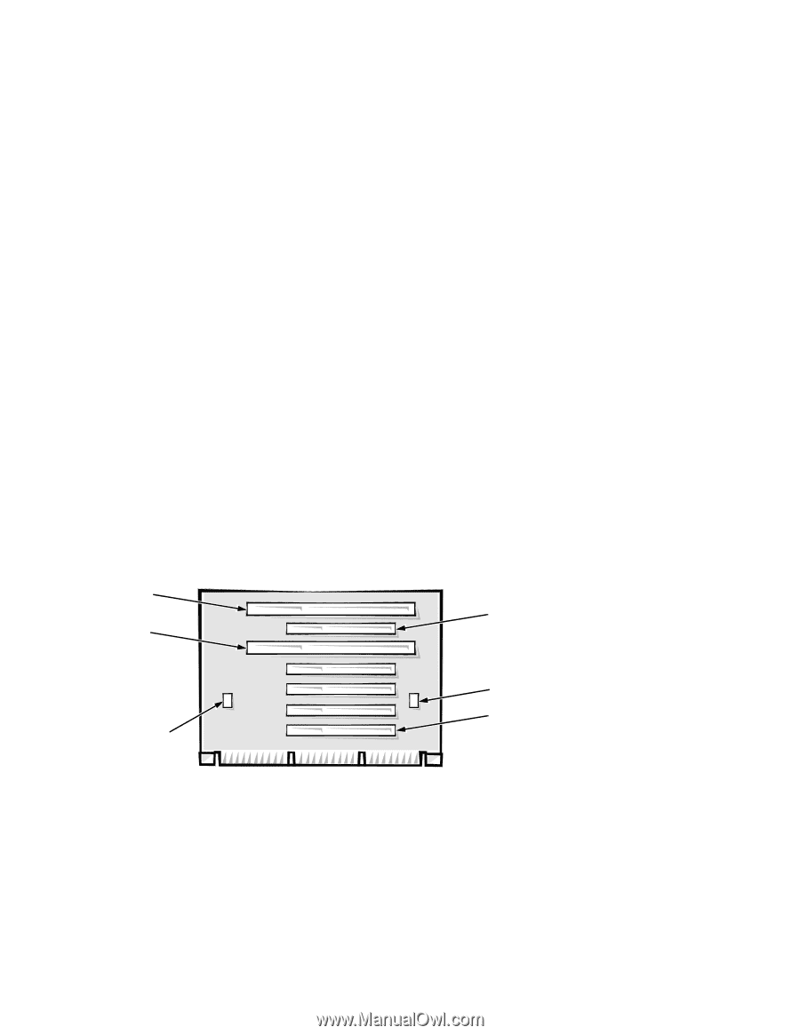
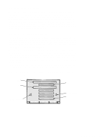
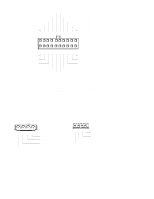
Dual-Processor Capability With the installation of a microprocessor add-in card in the terminator card slot, the system unit becomes a dual-processing system. The add-in card's microprocessor must have the same frequency and cache size as the system board's microprocessor. In order to take advantage of two processors, dual-processing systems must have multiprocessing operating systems, such as the Microsoft® Windows NT ® 3.5x, Windows NT 4.0, and Novell® NetWare® SMP (symmetric multiprocessing) operating systems. The microprocessor chips on both the system board and the processor card are replaceable. Advanced Expansion Subsystem The computer system offers advanced expansion subsystems that can support a mixture of traditional ISA expansion cards (called legacy cards), Plug and Play ISA expansion cards, and PCI expansion cards. The ISA Configuration Utility (ICU) included with the system provides a means of avoiding resource conflicts that might arise from such an arrangement. After all legacy cards have been configured with the ICU, the system automatically assigns any required memory space, IRQ lines, and DMA channels to any installed Plug and Play ISA expansion cards and PCI expansion cards the next time the system is rebooted. Chapter 4, "Using the ISA Configuration Utility," in the User's Guide describes the ICU and provides instructions for using it to configure the system. The five expansion slots include two ISA expansion-card connectors and five PCI expansion-card connectors. (Two PCI expansion-card connectors and the two ISA expansion-card connectors share a single expansion slot, resulting in a total of five expansion slots.) The expansion-card connectors are located on a riser board (see Figure 1-4). ISA2 ISA1 PCI 5 JHDLED connector JMIDI connector PCI1 Figure 1-4. Riser-Board Expansion-Card Connectors System Overview 1-5
-
 1
1 -
2
-
3
-
4
-
5
-
6
-
7
-
 8
8 -
 9
9 -
 10
10 -
 11
11 -
 12
12 -
 13
13 -
 14
14 -
 15
15 -
 16
16 -
 17
17 -
 18
18 -
19
-
20
-
21
-
22
-
23
-
24
-
25
-
26
-
27
-
28
-
29
-
30
-
31
-
32
-
33
-
34
-
35
-
36
-
37
-
38
-
39
-
40
-
41
-
42
-
43
-
44
-
45
-
46
-
47
-
48
-
49
-
50
-
51
-
52
-
53
-
54
-
55
-
56
-
57
-
58
-
59
-
60
-
61
-
62
-
63
-
64
-
65
-
66
-
67
-
68
-
69
-
70
-
71
-
72
-
73
-
74
-
75
-
76
-
77
-
78
-
79
-
80
 |
 |