Dell OptiPlex GL Service Manual - Page 50
Front-Panel Inserts, Front-Panel Insert Removal
 |
View all Dell OptiPlex GL manuals
Add to My Manuals
Save this manual to your list of manuals |
Page 50 highlights
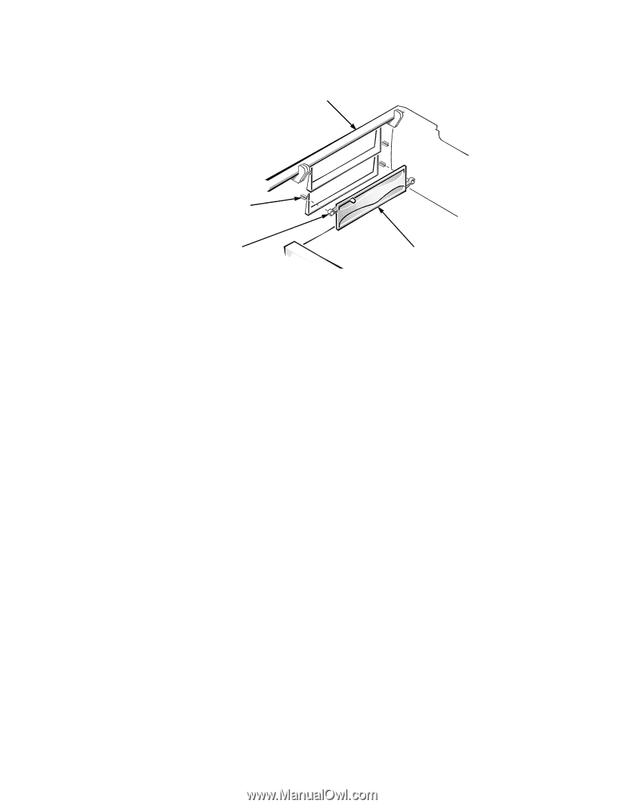
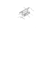
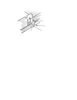
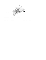
Front-Panel Inserts system unit cover (upside down) post (2) ring-tab (2) 5.25-inch frontpanel insert Figure 4-5. Front-Panel Insert Removal To remove a front-panel insert, follow these steps: 1. Lay the system unit cover upside down on a flat work surface, with the back of the cover facing you. 2. For a 5.25-inch bay, pull the insert from the two retaining posts until the ring-tabs are released (see Figure 4-5). For the 3.5-inch bay, locate the spring-loaded back end of the eject button mechanism. Press the mechanism toward the front panel to snap the plastic insert out of its opening (see Figure 4-4). To replace a front-panel insert for a 5.25-inch bay, position the insert over the drive bay opening. Place the panel over the retaining posts, and then press hard to get the ring-tabs over the posts. If necessary, use a 1/4-inch nutdriver to help push the ring-tabs. To replace the front-panel insert for the 3.5-inch bay, from outside the cover, place the insert in position and press it into the opening. 4-6 Dell OptiPlex GXpro Systems Service Manual
-
 1
1 -
2
-
3
-
4
-
5
-
6
-
7
-
8
-
9
-
10
-
11
-
12
-
13
-
14
-
15
-
16
-
17
-
18
-
19
-
20
-
21
-
22
-
23
-
24
-
25
-
26
-
27
-
28
-
29
-
30
-
31
-
32
-
33
-
34
-
35
-
36
-
37
-
38
-
39
-
40
-
41
-
42
-
43
-
44
-
 45
45 -
 46
46 -
 47
47 -
 48
48 -
 49
49 -
 50
50 -
 51
51 -
 52
52 -
 53
53 -
 54
54 -
 55
55 -
56
-
57
-
58
-
59
-
60
-
61
-
62
-
63
-
64
-
65
-
66
-
67
-
68
-
69
-
70
-
71
-
72
-
73
-
74
-
75
-
76
-
77
-
78
-
79
-
80
 |
 |