Dell OptiPlex GL Service Manual - Page 5

Appendix A, System Setup Program .A-1, Index, s, DC Power Connectors P2, P3, P4, P5

Page 5 highlights

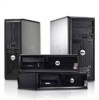
Terminator Card 4-23 Add-In Card 4-24 System Battery 4-25 System Board 4-26 Appendix A System Setup Program A-1 System Setup Screens A-2 Index Figures Figure 1-1. System Unit Orientation 1-3 Figure 1-2. Front-Panel Features 1-4 Figure 1-3. Internal View 1-4 Figure 1-4. Riser-Board Expansion-Card Connectors 1-5 Figure 1-5. DC Power Connector P1 1-9 Figure 1-6. DC Power Connectors P2, P3, P4, P5, and P6 1-9 Figure 1-7. DC Power Connectors P7 1-10 Figure 1-8. DC Power Cables 1-10 Figure 1-9. Power Distribution 1-11 Figure 1-10. System Board Components 1-12 Figure 1-11. System Board Jumpers 1-13 Figure 4-1. Floor Stand Removal 4-3 Figure 4-2. System-Unit Cover Removal 4-4 Figure 4-3. Padlock Removal 4-4 Figure 4-4. Eject, Power, and Reset Button Removal 4-5 Figure 4-5. Front-Panel Insert Removal 4-6 Figure 4-6. Indicator Card Removal 4-7 Figure 4-7. Speaker Removal 4-8 Figure 4-8. Drive Hardware 4-9 Figure 4-9. 3.5-Inch Diskette Drive Removal 4-10 Figure 4-10. 5.25-Inch Drive Removal 4-11 Figure 4-11. Hard-Disk Drive Bracket Removal 4-12 Figure 4-12. Hard-Disk Drive Removal 4-13 Figure 4-13. Power Supply Removal 4-14 Figure 4-14. Microprocessor Fan Removal 4-15 Figure 4-15. System Board Components 4-16 vii

  • 1
  • 2
  • 3
  • 4
  • 5
  • 6
  • 7
  • 8
  • 9
  • 10
  • 11
  • 12
  • 13
  • 14
  • 15
  • 16
  • 17
  • 18
  • 19
  • 20
  • 21
  • 22
  • 23
  • 24
  • 25
  • 26
  • 27
  • 28
  • 29
  • 30
  • 31
  • 32
  • 33
  • 34
  • 35
  • 36
  • 37
  • 38
  • 39
  • 40
  • 41
  • 42
  • 43
  • 44
  • 45
  • 46
  • 47
  • 48
  • 49
  • 50
  • 51
  • 52
  • 53
  • 54
  • 55
  • 56
  • 57
  • 58
  • 59
  • 60
  • 61
  • 62
  • 63
  • 64
  • 65
  • 66
  • 67
  • 68
  • 69
  • 70
  • 71
  • 72
  • 73
  • 74
  • 75
  • 76
  • 77
  • 78
  • 79
  • 80

vii
Terminator Card . . . . . . . . . . . . . . . . . . . . . . . . . . . . . . . . . . . . . . . . 4-23
Add-In Card . . . . . . . . . . . . . . . . . . . . . . . . . . . . . . . . . . . . . . . . . . .4-24
System Battery . . . . . . . . . . . . . . . . . . . . . . . . . . . . . . . . . . . . . . . . . . . . 4-25
System Board . . . . . . . . . . . . . . . . . . . . . . . . . . . . . . . . . . . . . . . . . . . . . . . . 4-26
Appendix A
System Setup Program . . . . . . . . . . . . . . . . . . . . . . . . . . A-1
System Setup Screens . . . . . . . . . . . . . . . . . . . . . . . . . . . . . . . . . . . . . . . . . . .A-2
Index
Figures
Figure 1-1.
System Unit Orientation. . . . . . . . . . . . . . . . . . . . . . . . . . . . . . 1-3
Figure 1-2.
Front-Panel Features . . . . . . . . . . . . . . . . . . . . . . . . . . . . . . . .1-4
Figure 1-3.
Internal View . . . . . . . . . . . . . . . . . . . . . . . . . . . . . . . . . . . . . . 1-4
Figure 1-4.
Riser-Board Expansion-Card Connectors . . . . . . . . . . . . . . . . 1-5
Figure 1-5.
DC Power Connector P1 . . . . . . . . . . . . . . . . . . . . . . . . . . . . . 1-9
Figure 1-6.
DC Power Connectors P2, P3, P4, P5, and P6. . . . . . . . . . . . . 1-9
Figure 1-7.
DC Power Connectors P7 . . . . . . . . . . . . . . . . . . . . . . . . . . .1-10
Figure 1-8.
DC Power Cables . . . . . . . . . . . . . . . . . . . . . . . . . . . . . . . . . . 1-10
Figure 1-9.
Power Distribution . . . . . . . . . . . . . . . . . . . . . . . . . . . . . . . . . 1-11
Figure 1-10.
System Board Components . . . . . . . . . . . . . . . . . . . . . . . . . . 1-12
Figure 1-11.
System Board Jumpers. . . . . . . . . . . . . . . . . . . . . . . . . . . . . . 1-13
Figure 4-1.
Floor Stand Removal . . . . . . . . . . . . . . . . . . . . . . . . . . . . . . . . 4-3
Figure 4-2.
System-Unit Cover Removal . . . . . . . . . . . . . . . . . . . . . . . . . . 4-4
Figure 4-3.
Padlock Removal . . . . . . . . . . . . . . . . . . . . . . . . . . . . . . . . . . . 4-4
Figure 4-4.
Eject, Power, and Reset Button Removal . . . . . . . . . . . . . . . .4-5
Figure 4-5.
Front-Panel Insert Removal . . . . . . . . . . . . . . . . . . . . . . . . . . . 4-6
Figure 4-6.
Indicator Card Removal . . . . . . . . . . . . . . . . . . . . . . . . . . . . . . 4-7
Figure 4-7.
Speaker Removal . . . . . . . . . . . . . . . . . . . . . . . . . . . . . . . . . . . 4-8
Figure 4-8.
Drive Hardware . . . . . . . . . . . . . . . . . . . . . . . . . . . . . . . . . . . . 4-9
Figure 4-9.
3.5-Inch Diskette Drive Removal . . . . . . . . . . . . . . . . . . . . .4-10
Figure 4-10.
5.25-Inch Drive Removal. . . . . . . . . . . . . . . . . . . . . . . . . . . . 4-11
Figure 4-11.
Hard-Disk Drive Bracket Removal . . . . . . . . . . . . . . . . . . . . 4-12
Figure 4-12.
Hard-Disk Drive Removal . . . . . . . . . . . . . . . . . . . . . . . . . . . 4-13
Figure 4-13.
Power Supply Removal . . . . . . . . . . . . . . . . . . . . . . . . . . . . . 4-14
Figure 4-14.
Microprocessor Fan Removal . . . . . . . . . . . . . . . . . . . . . . . . 4-15
Figure 4-15.
System Board Components . . . . . . . . . . . . . . . . . . . . . . . . . . 4-16