Dell OptiPlex GL Service Manual - Page 20
System Board Layout, Video Memory
 |
View all Dell OptiPlex GL manuals
Add to My Manuals
Save this manual to your list of manuals |
Page 20 highlights
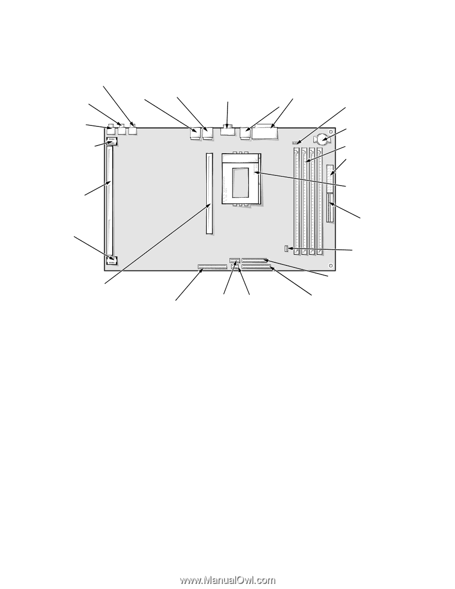
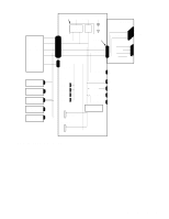
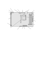
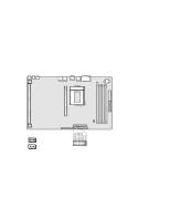
microphone jack (NIC-IN) speaker-out jack (SPKR-OUT) line-in jack (LINE-IN) riser board power connector (RSR PWR1) System Board Layout The subsections that follow provide service-related information about the system board components. NIC connector (ENET) USB connector (USB) serial port 2 connector (SERIAL2) keyboard/mouse connectors (stacked) (KYBD/MOUSE) serial port 1/parallel port connectors (stacked) (PARALLEL/SERIAL) microprocessor fan connector (FAN) battery socket (BATTERY) DIMM sockets (4) main power input connector (POWER1) riser board connector (RISER) microprocessor socket (MICROPROCESSOR) riser board power connector (RSR PWR2) 3.3-V power input connectors (POWER2) CD-ROM connector (CD_IN) secondary microprocessor card (or terminator card) connector (2ND_CPU) front of system unit primary EIDE interface connector (IDE1) jumpers control panel connector (PANEL) diskette/tape drive interface connector (DSKT) secondary EIDE interface connector (IDE2) Figure 1-10. System Board Components Video Memory See the documentation from the video card manufacturer that came with your system for information on removing and replacing video-memory upgrade chips. 1-12 Dell OptiPlex GXpro Systems Service Manual
-
 1
1 -
2
-
3
-
4
-
5
-
6
-
7
-
8
-
9
-
10
-
11
-
12
-
13
-
14
-
 15
15 -
 16
16 -
 17
17 -
 18
18 -
 19
19 -
 20
20 -
 21
21 -
 22
22 -
 23
23 -
 24
24 -
 25
25 -
26
-
27
-
28
-
29
-
30
-
31
-
32
-
33
-
34
-
35
-
36
-
37
-
38
-
39
-
40
-
41
-
42
-
43
-
44
-
45
-
46
-
47
-
48
-
49
-
50
-
51
-
52
-
53
-
54
-
55
-
56
-
57
-
58
-
59
-
60
-
61
-
62
-
63
-
64
-
65
-
66
-
67
-
68
-
69
-
70
-
71
-
72
-
73
-
74
-
75
-
76
-
77
-
78
-
79
-
80
 |
 |