Foxconn Inferno Katana English Manual. - Page 30
Early CPU Init Start -- Disable Cache - Init Local APIC.
 |
View all Foxconn Inferno Katana manuals
Add to My Manuals
Save this manual to your list of manuals |
Page 30 highlights
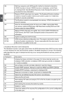
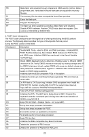
FB Make flash write enabled through chipset and OEM specific method. Detect proper flash part. Verify that the found flash part size equals the recovery file size. F4 The recovery file size does not equal the found flash part size. FC Erase the flash part. FD Program the flash part. FF The flash has been updated successfully. Make flash write disabled. Disable ATAPI hardware. Restore CPUID value back into register. Give control to F000 ROM at F000:FFF0h. 2 3. POST Code Checkpoints The POST code checkpoints are the largest set of checkpoints during the BIOS preboot process. The following table describes the type of checkpoints that may occur during the POST portion of the BIOS: Checkpoint Description 03 Disable NMI, Parity, video for EGA, and DMA controllers. Initialize BIOS, POST, Runtime data area. Also initialize BIOS modules on POST entry and GPNV area. Initialized CMOS as mentioned in the Kernel Variable "wCMOSFlags." 04 Check CMOS diagnostic byte to determine if battery power is OK and CMOS checksum is OK. Verify CMOS checksum manually by reading storage area. If the CMOS checksum is bad, update CMOS with power-on default values and clear passwords. Initialize status register A. Initializes data variables that are based on CMOS setup questions. Initializes both the 8259 compatible PICs in the system. 05 Initializes the interrupt controlling hardware (generally PIC) and interrupt vector table. 06 Do R/W test to CH-2 count reg. Initialize CH-0 as system timer. Install the POSTINT1Ch handler. Enable IRQ-0 in PIC for system timer interrupt. Traps INT1Ch vector to "POSTINT1ChHandlerBlock." 07 Fixes CPU POST interface calling pointer. 08 Initializes the CPU. The BAT test is being done on KBC. Program the keyboard controller command byte is being done after Auto detection of KB/MS using AMI KB-5. C0 Early CPU Init Start -- Disable Cache - Init Local APIC. C1 Set up boot strap processor Information. C2 Set up boot strap processor for POST. C5 Enumerate and set up application processors. C6 Re-enable cache for boot strap processor. C7 Early CPU Init Exit. 0A Initializes the 8042 compatible Key Board Controller. 0B Detects the presence of PS/2 mouse. 0C Detects the presence of Keyboard in KBC port. 23 23
-
 1
1 -
2
-
3
-
4
-
5
-
6
-
7
-
8
-
9
-
10
-
11
-
12
-
13
-
14
-
15
-
16
-
17
-
18
-
19
-
20
-
21
-
22
-
23
-
24
-
 25
25 -
 26
26 -
 27
27 -
 28
28 -
 29
29 -
 30
30 -
 31
31 -
 32
32 -
 33
33 -
 34
34 -
 35
35 -
36
-
37
-
38
-
39
-
40
-
41
-
42
-
43
-
44
-
45
-
46
-
47
-
48
-
49
-
50
-
51
-
52
-
53
-
54
-
55
-
56
-
57
-
58
-
59
-
60
-
61
-
62
-
63
-
64
-
65
-
66
-
67
-
68
-
69
-
70
-
71
-
72
-
73
-
74
-
75
-
76
-
77
-
78
-
79
-
80
-
81
-
82
-
83
-
84
-
85
-
86
-
87
-
88
-
89
-
90
-
91
-
92
-
93
-
94
-
95
-
96
-
97
-
98
-
99
-
100
-
101
-
102
-
103
-
104
-
105
-
106
-
107
-
108
-
109
-
110
-
111
-
112
-
113
-
114
-
115
-
116
-
117
-
118
-
119
-
120
-
121
-
122
-
123
-
124
 |
 |
