Gigabyte GA-M750SLI-DS4 Manual
Gigabyte GA-M750SLI-DS4 Manual
 |
View all Gigabyte GA-M750SLI-DS4 manuals
Add to My Manuals
Save this manual to your list of manuals |
Gigabyte GA-M750SLI-DS4 manual content summary:
- Gigabyte GA-M750SLI-DS4 | Manual - Page 1
GA-M750SLI-DS4 AM2+/AM2 socket motherboard for AMD PhenomTM FX processor/AMD PhenomTM X4 processor/ AMD PhenomTM X3 processor/AMD AthlonTM X2 processor/ AMD AthlonTM processor/AMD SempronTM X2 processor AMD SempronTM processor User's Manual Rev. 1002 12ME-M75SLID4-1002R - Gigabyte GA-M750SLI-DS4 | Manual - Page 2
Motherboard GA-M750SLI-DS4 May 15, 2008 Motherboard GA-M750SLI-DS4 May 15, 2008 - Gigabyte GA-M750SLI-DS4 | Manual - Page 3
with the product. „ For detailed product information, carefully read the User's Manual. „ For instructions on how to use GIGABYTE's unique features, read or download the information on/from the Support\Motherboard\Technology Guide page on our website. For product-related information, check on our - Gigabyte GA-M750SLI-DS4 | Manual - Page 4
Table of Contents Box Contents ...6 OptionalItems ...6 GA-M750SLI-DS4 Motherboard Layout 7 Block Diagram ...8 Chapter 1 Hardware Installation 1-6 Setup of an SLI (Scalable Link Interface) Configuration 19 1-7 Back Panel Connectors 21 1-8 Internal Connectors 23 Chapter 2 BIOS Setup 35 2-1 Startup - Gigabyte GA-M750SLI-DS4 | Manual - Page 5
Driver CD Information 60 3-4 Hardware Information 61 3-5 Contact Us ...61 Chapter 4 Unique Features 63 4-1 Xpress Recovery2 63 4-2 BIOS Update Utilities 68 4-2-1 Updating the BIOS with the Q-Flash Utility 68 4-2-2 Updating the BIOS with the @BIOS Utility 71 4-3 EasyTune 5 Pro 73 4-4 Windows - Gigabyte GA-M750SLI-DS4 | Manual - Page 6
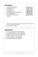
Box Contents GA-M750SLI-DS4 motherboard Motherboard driver disk User's Manual Quick Installation Guide One IDE cable and one floppy disk drive cable Four SATA 3Gb/s cables One GC-DGBR2-RH (SLI Bridge) I/O Shield • The box contents above are for reference only and the actual items shall depend on - Gigabyte GA-M750SLI-DS4 | Manual - Page 7
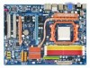
DDR2_3 DDR2_4 SATA2_4 SATA2_5 GA-M750SLI-DS4 Motherboard Layout KB_USB CPU_FAN ATX_12V_2X4 RCA_SPDIF ATX VGA_DVI Socket AM2 PWR_FAN USB_1394 IDE USB_LAN1 F_AUDIO AUDIO RTL8211B PCIE_12V GA-M750SLI-DS4 PCIEX16_1 PCIEX1_1 B_BIOS NVIDIA® nForce® 750a SLI PCIEX1_2 CODEC CD_IN M_BIOS - Gigabyte GA-M750SLI-DS4 | Manual - Page 8
MHz) or AMD Socket AM2+/AM2 CPU CPU CLK+/- (200 MHz) DDR2 1066/800/667 MHz Dual Channel Memory Hyper Transport 3.0 Normal Mode SLI Mode Switch PCI Sub DVI-D NVIDIA® nForce® 750a SLI 6 SATA 3Gb/s 12 USB Ports CODEC ATA-133/100/66/33 IDE Channel LPC Bus IT8720 Dual BIOS Floppy LPT Port - Gigabyte GA-M750SLI-DS4 | Manual - Page 9
, carefully read the user's manual and follow these procedures: • Prior to installation, do not remove or break motherboard S/N (Serial Number) sticker or you are uncertain about any installation steps or have a problem related to the use of the product, please consult a certified computer technician. - Gigabyte GA-M750SLI-DS4 | Manual - Page 10
1394a ports (1 on the back panel, 2 via the IEEE 1394a brackets connected to the internal IEEE 1394a headers) Integrated in the NVIDIA® nForce® 750a SLI Up to 12 USB 2.0/1.1 ports (6 on the back panel, 6 via the USB brackets connected to the internal USB headers) GA-M750SLI-DS4 Motherboard - 10 - - Gigabyte GA-M750SLI-DS4 | Manual - Page 11
Internal Connectors Š 1 x 24-pin ATX main power connector Š 1 x 8-pin ATX 12V power connector Š 1 x 4-pin PCIe 12V power connector Š 1 x floppy disk drive connector Š 1 x IDE connector Š 6 x SATA 3Gb/s connectors Š 1 x CPU fan header Š 2 x system fan headers Š 1 x power fan - Gigabyte GA-M750SLI-DS4 | Manual - Page 12
4) The DVI-D port does not support D-Sub connection by adapter. (Note 5) Whether the CPU/system fan speed control function is supported will depend on the CPU/ system cooler you install. (Note 6) Available functions in EasyTune may differ by motherboard model. GA-M750SLI-DS4 Motherboard - 12 - - Gigabyte GA-M750SLI-DS4 | Manual - Page 13
• Make sure that the motherboard supports the CPU. (Go to GIGABYTE's website for the latest CPU support list.) • Always turn off motherboard CPU socket and the notches on the CPU. A Small Triangle Mark Denotes Pin One of the Socket AM2 Socket A Small Triangle Marking Denotes CPU Pin One AM2+/AM2 - Gigabyte GA-M750SLI-DS4 | Manual - Page 14
into its socket, place one finger down on the middle of the CPU, lowering the locking lever and latching it into the fully locked position. Do not force the CPU into the CPU socket. The CPU cannot fit in if oriented incorrectly. Adjust the CPU orientation if this occurs. GA-M750SLI-DS4 Motherboard - Gigabyte GA-M750SLI-DS4 | Manual - Page 15
the CPU cooler on the CPU. (The following procedure uses the GIGABYTE cooler as the example.) Step 1: Apply an even and thin layer manual for instructions on installing the cooler.) Step 5: Finally, attach the power connector of the CPU cooler to the CPU fan header (CPU_FAN) on the motherboard - Gigabyte GA-M750SLI-DS4 | Manual - Page 16
that the motherboard supports the memory. It is recommended that memory of the same capacity, brand, speed, and chips be used. (Go to GIGABYTE's website for the latest memory support list.) • and installed in the same colored DDR2 sockets for optimum performance. GA-M750SLI-DS4 Motherboard - 16 - - Gigabyte GA-M750SLI-DS4 | Manual - Page 17
are not compatible to DDR DIMMs. Be sure to install DDR2 DIMMs on this motherboard. Notch DDR2 DIMM A DDR2 memory module has a notch, so it can only Spread the retaining clips at both ends of the memory socket. Place the memory module on the socket. As indicated in the picture on the left, place - Gigabyte GA-M750SLI-DS4 | Manual - Page 18
Make sure the motherboard supports the expansion card. Carefully read the manual that came with BIOS Setup to make any required BIOS changes for your expansion card(s). 7. Install the driver up from the slot. GA-M750SLI-DS4 Motherboard - 18 - • The motherboard provides a PCIE_12V power connector - Gigabyte GA-M750SLI-DS4 | Manual - Page 19
(Scalable Link Interface) Configuration The NVIDIA® nForce® 750a SLI chipset offers blistering graphics performance with the ability to bridge two NVIDIA SLI-ready PCI ExpressTM graphics cards! This section provides instructions on configuring an SLI system. A. Before you begin-1. Power Requirements - Gigabyte GA-M750SLI-DS4 | Manual - Page 20
SLI mode is enabled. (The SLI configuration screen may differ by driver version.) Procedure for enabling SLI technology may slightly differ by graphics cards. Refer to the manual that came with your graphics cards for more information about enabling SLI technology. GA-M750SLI-DS4 Motherboard - Gigabyte GA-M750SLI-DS4 | Manual - Page 21
connector provides digital audio out to an external audio system that supports digital optical audio. Before using this feature, ensure that your , first remove the cable from your device and then remove it from the motherboard. • When removing the cable, pull it straight out from the connector. - Gigabyte GA-M750SLI-DS4 | Manual - Page 22
perform different functions via the audio software. Only microphones still MUST be connected to the default Mic in jack ( ). Refer to the instructions on setting up a 2/4/5.1/ 7.1-channel audio configuration in Chapter 5, "Configuring 2/4/5.1/7.1-Channel Audio." GA-M750SLI-DS4 Motherboard - 22 - - Gigabyte GA-M750SLI-DS4 | Manual - Page 23
1-8 Internal Connectors 1 3 8 2 5 12 9 6 22 13 9 15 17 14 4 21 19 1) ATX_12V_2X4 2) ATX 3) CPU_FAN 4) SYS_FAN1 / SYS_FAN2 5) PWR_FAN 6) PCIE_12V 7) FDD 8) IDE 9) SATA2_0 / 1 / 2 / 3 / 4 / 5 10) PWR_LED securely attached to the connector on the motherboard. - 23 - Hardware Installation - Gigabyte GA-M750SLI-DS4 | Manual - Page 24
16 GND 17 +5V 18 GND 19 Power Good 20 5V SB(stand by +5V) 21 +12V 22 +12V(Onlyfor2x12pin ATX) 23 3.3V(Onlyfor2x12pin ATX) 24 Definition 3.3V -12V GND PS_ON(soft On/Off) GND GND GND -5V +5V +5V +5V (Only for 2x12 pin ATX) GND (Only for 2x12 pin ATX) GA-M750SLI-DS4 Motherboard - 24 - - Gigabyte GA-M750SLI-DS4 | Manual - Page 25
connector wires. A red power connector wire indicates a positive connection and requires a +12V voltage. The black connector wire is the ground wire. The motherboard supports CPU fan speed control, which requires the use of a CPU fan with fan speed control design. For optimum heat dissipation, it is - Gigabyte GA-M750SLI-DS4 | Manual - Page 26
stripe of different color. 33 1 34 2 8) IDE (IDE Connector) The IDE connector supports up to two IDE devices such as hard drives and optical drives. Before attaching the IDE the IDE devices, read the instructions from the device manufacturers.) 40 39 GA-M750SLI-DS4 Motherboard 2 1 - 26 - - Gigabyte GA-M750SLI-DS4 | Manual - Page 27
supports a single SATA device. The NVIDIA nForce 750a SLI controller supports RAID 0, RAID 1, RAID 0+1 and RAID 5. Refer to Chapter 5, "Configuring SATA Hard Drive(s)," for instructions The LED is off when the system is in S3/S4 sleep state or powered off (S5). Pin No. Definition 1 MPD+ 2 MPD - Gigabyte GA-M750SLI-DS4 | Manual - Page 28
LED is off when the system is in S3/S4/S5 Off S3/S4 sleep state or powered off (S5). • PW problem is detected at system startup. If a problem is detected, the BIOS may issue beeps in different patterns to indicate the problem. Refer to Chapter 5, "Troubleshooting GA-M750SLI-DS4 Motherboard - 28 - - Gigabyte GA-M750SLI-DS4 | Manual - Page 29
the pin assignments of the motherboard header. Incorrect connection between the module connector and the motherboard header will make the device panel audio header supports HD audio by default. If your chassis provides an AC'97 front panel audio module, refer to the instructions on how to - Gigabyte GA-M750SLI-DS4 | Manual - Page 30
This header supports digital S/PDIF out and connects a S/PDIF digital audio cable (provided by expansion cards) for digital audio output from your motherboard to certain , carefully read the manual for your expansion card. Pin No. Definition 1 1 SPDIFO 2 GND GA-M750SLI-DS4 Motherboard - 30 - - Gigabyte GA-M750SLI-DS4 | Manual - Page 31
16) F1_1394_1/F1_1394_2 (IEEE 1394a Headers, Gray) The headers conform to IEEE 1394a specification. Each IEEE 1394a header can provide one IEEE 1394a port via an optional IEEE 1394a bracket. For purchasing the optional IEEE 1394a bracket, please contact the local dealer. 12 Pin No. Definition - Gigabyte GA-M750SLI-DS4 | Manual - Page 32
16 17 18 19 20 21 22 23 24 25 26 Definition GND PD6 GND PD7 GND ACKGND BUSY GND PE No Pin SLCT GND GA-M750SLI-DS4 Motherboard - 32 - - Gigabyte GA-M750SLI-DS4 | Manual - Page 33
jumper. Failure to do so may cause damage to the motherboard. • After system restart, go to BIOS Setup to load factory defaults (select Load Optimized Defaults) or manually configure the BIOS settings (refer to Chapter 2, "BIOS Setup," for BIOS configurations). 21) CI (Chassis Intrusion Header) This - Gigabyte GA-M750SLI-DS4 | Manual - Page 34
22) BATTERY The battery provides power to keep the values (such as BIOS configurations, date, and time information) in the CMOS when the computer is turned off should face up). • Used batteries must be handled in accordance with local environmental regulations. GA-M750SLI-DS4 Motherboard - 34 - - Gigabyte GA-M750SLI-DS4 | Manual - Page 35
Windows-based utility that searches and downloads the latest version of BIOS from the Internet and updates the BIOS. For instructions on using the Q-Flash and @BIOS utilities, refer to Chapter 4, "BIOS Update Utilities." • Because BIOS flashing is potentially risky, if you do not encounter problems - Gigabyte GA-M750SLI-DS4 | Manual - Page 36
:Boot Menu :Qflash Function Keys B. The POST Screen Motherboard Model BIOS Version Award Modular BIOS v6.00PG, An Energy Star Ally Copyright (C) 1984-2008, Award Software, Inc. M750SLI-DS4 D28 . . . . : BIOS Setup : XpressRecovery2 : Boot Menu : Qflash - Gigabyte GA-M750SLI-DS4 | Manual - Page 37
Exit Setup Exit Without Saving ESC: Quit F8: Q-Flash KLJI: Select Item F10: Save & Exit Setup F11: Save CMOS to BIOS F12: Load CMOS from BIOS Time, Date, Hard Disk Type... BIOS Setup Program Function Keys Move the selection bar to select an item Execute command or enter the submenu - Gigabyte GA-M750SLI-DS4 | Manual - Page 38
and exit BIOS Setup. (Pressing can also carry out this task.) „ Exit Without Saving Abandon all changes and the previous settings remain in effect. Pressing to the confirmation message will exit BIOS Setup. (Pressing can also carry out this task.) GA-M750SLI-D4 Motherboard - 38 - Gigabyte GA-M750SLI-DS4 | Manual - Page 39
the overclock/overvoltage settings you made is dependent on your overall system configurations. Incorrectly doing overclock/ Allows you to manually set the frequency for the HT Link between the CPU and chipset. Auto BIOS will automatically adjust the supports this feature. - 39 - BIOS Setup - Gigabyte GA-M750SLI-DS4 | Manual - Page 40
SLI-Ready Memory Allows you to enable or disable the SLI-Ready (EPP) memory function. (Default: Disabled) Set Memory Clock Determines whether to manually set the memory clock. Auto lets BIOS This item appears only if you install a CPU that supports this feature. GA-M750SLI-D4 Motherboard - 40 - - Gigabyte GA-M750SLI-DS4 | Manual - Page 41
Auto (default), 2T~5T. ******** System Voltage Optimized ******** System Voltage Control Determines whether to manually set the system voltages. Auto lets BIOS automatically set the system voltages as required. Manual allows all voltage control items below to be configurable. (Default: Auto) - 41 - Gigabyte GA-M750SLI-DS4 | Manual - Page 42
life of the CPU. Normal CPU Vcore Displays the normal operating voltage of your CPU. (Note) This item appears only if you install a CPU that supports this feature. GA-M750SLI-D4 Motherboard - 42 - - Gigabyte GA-M750SLI-DS4 | Manual - Page 43
[None] [None] [None] [None] [None] Drive A Floppy 3 Mode Support [1.44M, 3.5"] [Disabled] Halt On [All, But Keyboard] Base Memory Extended Memory methods below: • Auto • None • Manual Access Mode Lets BIOS automatically detect IDE/SATA devices during the POST. (Default) If no IDE/SATA devices - Gigabyte GA-M750SLI-DS4 | Manual - Page 44
parameters manually, 44M/3.5", 2.88M/3.5". Floppy 3 Mode Support Allows you to specify whether the BIOS POST. Base Memory Also called conventional memory. Typically, 640 KB will be reserved for the MS-DOS operating system. Extended Memory The amount of extended memory. GA-M750SLI-D4 Motherboard - Gigabyte GA-M750SLI-DS4 | Manual - Page 45
Software Advanced BIOS Features Virtualization Away Mode Full Screen LOGO Show x Hybrid SLI (Note 2) x Display Detection (Note 2) control Auto Lets the AMD Cool'n'Quiet driver dynamically adjust the CPU clock and VIA to supports this feature. (Note 2) This item appears only if you install a - Gigabyte GA-M750SLI-DS4 | Manual - Page 46
use only this memory for display. This item is configurable only if the iGPU Frame Buffer Control option is set to Manual. Options are: 128M (default), 256M, 512M, Disabled. (Note 2) This item appears only if you install a graphics card that supports this feature. GA-M750SLI-D4 Motherboard - 46 - - Gigabyte GA-M750SLI-DS4 | Manual - Page 47
VGA, whether or not a PCI Express card is installed. If you wish to set up a dual view configuration, set this item to Always Enable. - 47 - BIOS Setup - Gigabyte GA-M750SLI-DS4 | Manual - Page 48
Mode x ECP Mode Use DMA On-Chip USB USB Memory Type USB Keyboard Support USB Mouse Support Legacy USB storage detect [Enabled] [Enabled] [IDE] [Auto] [Auto] is an interface specification that allows the storage driver to enable advanced Serial ATA features such as GA-M750SLI-D4 Motherboard - 48 - - Gigabyte GA-M750SLI-DS4 | Manual - Page 49
motherboard incorporates cable diagnostic feature designed to detect the status of the attached LAN cable. This feature will detect cabling issue 10/100/1000 Mbps in Windows mode or when the LAN Boot ROM is activated. When a Cable Problem Occurs... If a cable problem occurs on a specified BIOS Setup - Gigabyte GA-M750SLI-DS4 | Manual - Page 50
-DOS. (Default: Disabled) USB Mouse Support Allows USB mouse to be used in MS-DOS. (Default: Disabled) Legacy USB storage detect Determines whether to detect USB storage devices, including USB flash drives and USB hard drives during the POST. (Default: Enabled) GA-M750SLI-D4 Motherboard - 50 - - Gigabyte GA-M750SLI-DS4 | Manual - Page 51
from a PCI or PCIe device. Note: To use this function, you need an ATX power supply providing at least 1A on the +5VSB lead. (Default: Enabled) Modem from a modem that supports wake-up function. (Default: Enabled) (Note) Supported on Windows® Vista® operating system only. - 51 - BIOS Setup - Gigabyte GA-M750SLI-DS4 | Manual - Page 52
the system to be turned on by a PS/2 keyboard wake-up event. Note: you need an ATX power supply providing at least 1A on the +5VSB lead. Disabled Password Keyboard 98 Any KEY Disables of the AC power. (Note) Supported on Windows® Vista® operating system only. GA-M750SLI-D4 Motherboard - 52 - - Gigabyte GA-M750SLI-DS4 | Manual - Page 53
IRQ Assignment Auto 3,4,5,7,9,10,11,12,14,15 +/-/PU/PD: Value F10: Save F6: Fail-Safe Defaults ESC: Exit F1: General Help F7: Optimized Defaults BIOS auto-assigns IRQ to the first PCI slot. (Default) Assigns IRQ 3,4,5,7,9,10,11,12,14,15 to the first PCI slot - Gigabyte GA-M750SLI-DS4 | Manual - Page 54
the motherboard CI header. If the system chassis cover is removed, this field will show "Yes", otherwise it will show "No". To clear the chassis intrusion status record, set Reset Case Open Status to Enabled, save the settings to CMOS, and then restart your system. GA-M750SLI-D4 Motherboard - 54 - Gigabyte GA-M750SLI-DS4 | Manual - Page 55
system/CPU temperature. When system/CPU temperature exceeds the threshold, BIOS will emit warning sound. Options are: Disabled (default), 60oC/ only if CPU Smart FAN Control is set to Enabled. Auto Voltage PWM Lets BIOS autodetect the type of CPU fan installed and sets the optimal CPU fan control - Gigabyte GA-M750SLI-DS4 | Manual - Page 56
Press on this item and then press the key to load the optimal BIOS default settings. The BIOS defaults settings helps the system to operate in optimum state. Always load the Optimized defaults after updating the BIOS or after clearing the CMOS values. GA-M750SLI-D4 Motherboard - 56 - - Gigabyte GA-M750SLI-DS4 | Manual - Page 57
Password Save & Exit Setup Exit Without Saving ESC: Quit F8: Q-Flash KLJI: Select Item F10: Save & Exit Setup F11: Save CMOS to BIOS F12: Load CMOS from BIOS Change/Set/Disable Password Press on this item and type the password with up to 8 characters and then press . You will be - Gigabyte GA-M750SLI-DS4 | Manual - Page 58
F11: Save CMOS to BIOS F12: Load CMOS from BIOS Abandon all Data Press on this item and press the key. This exits the BIOS Setup without saving the changes made in BIOS Setup to the CMOS. Press or to return to the BIOS Setup Main Menu. GA-M750SLI-D4 Motherboard - 58 - - Gigabyte GA-M750SLI-DS4 | Manual - Page 59
other drivers. • After the drivers are installed, follow the onscreen instructions to restart your system. You can install other applications included in the motherboard driver disk. • For USB 2.0 driver support under the Windows XP operating system, please install the Windows XP Service Pack - Gigabyte GA-M750SLI-DS4 | Manual - Page 60
all the tools and applications that GIGABYTE develops and some free software. You may press the Install button following an item to install it. 3-3 Driver CD Information This page provides information about the drivers, applications and tools in this driver disk. GA-M750SLI-DS4 Motherboard - 60 - - Gigabyte GA-M750SLI-DS4 | Manual - Page 61
3-4 Hardware Information This page provides information about the hardware devices on this motherboard. 3-5 Contact Us Check the contacts information of the GIGABYTE headquarter in Taiwan and the overseas branch offices on the last page of this manual. - 61 - Drivers Installation - Gigabyte GA-M750SLI-DS4 | Manual - Page 62
GA-M750SLI-DS4 Motherboard - 62 - - Gigabyte GA-M750SLI-DS4 | Manual - Page 63
system data and perform restoration of it. Supporting NTFS, FAT32, and FAT16 file systems, Xpress up your system soon after the operating system and drivers are installed. • The amount of data and hard of system memory • VESA compatible graphics card • Windows® XP with SP1 or later • Xpress Recovery - Gigabyte GA-M750SLI-DS4 | Manual - Page 64
Windows XP as the example operating system.) A. Installing Windows XP and Partitioning the Hard Drive 1. Set CD-ROM drive as the first boot device under "Advanced BIOS Features" in the BIOS ) and begin the installation of the operating system (Figure 3). Figure 3 GA-M750SLI-DS4 Motherboard - 64 - - Gigabyte GA-M750SLI-DS4 | Manual - Page 65
4. After the operating system is installed, right-click the My Computer icon on your desktop and select Manage (Figure 4). Go to Computer Management to check disk allocation. Xpress Recovery2 will save the backup file to the unallocated space (black stripe along the top)(Figure 5). Please note that - Gigabyte GA-M750SLI-DS4 | Manual - Page 66
operating system. When the Windows operating system is detected, Xpress Recovery2 will begin the backup process (Figure 11). Figure 10 Figure 11 3. When finished, go to Disk Management to check disk allocation. Figure 12 GA-M750SLI-DS4 Motherboard Xpress Recovery2 will automatically create - Gigabyte GA-M750SLI-DS4 | Manual - Page 67
D. Using the Restore Function in Xpress Recovery2 Select RESTORE to restore the backup to your hard drive in case the system breaks down. The RESTORE option will not be present if no backup is created before (Figure 13, 14). Figure 13 Figure 14 E. Removing the Backup 1. If you wish to remove the - Gigabyte GA-M750SLI-DS4 | Manual - Page 68
, Inc. M750SLI-DS4 D28 . . . . : BIOS Setup : XpressRecovery2 : Boot Menu : Qflash 04/30/2008-NF-MCP78-6A61OG04C-00 Because BIOS flashing is potentially risky, please do it with caution. Inadequate BIOS flashing may result in system malfunction. GA-M750SLI-DS4 Motherboard - 68 - Gigabyte GA-M750SLI-DS4 | Manual - Page 69
save the current BIOS file. • Q-Flash only supports USB flash drive or hard drives using FAT32/16/12 file system. • If the BIOS update file is saved to a hard drive in RAID/AHCI mode or a hard drive attached to an independent IDE/SATA controller, use the key during the POST to access Q-Flash - Gigabyte GA-M750SLI-DS4 | Manual - Page 70
Setup F11: Save CMOS to BIOS F12: Load CMOS from BIOS Load Optimized Defaults Press to load BIOS defaults Step 6: Select Save & Exit Setup and then press to save settings to CMOS and exit BIOS Setup. The procedure is complete after the system restarts. GA-M750SLI-DS4 Motherboard - 70 - - Gigabyte GA-M750SLI-DS4 | Manual - Page 71
and Using @BIOS: Use the motherboard driver disk included with the motherboard to install @BIOS. • Installing the @BIOS utility. • Accessing the @BIOS utility. Click Start>All Programs>GIGABYTE> @BIOS Select @BIOS and click Install. C. Options and Instructions: 1. Save the Current BIOS File In - Gigabyte GA-M750SLI-DS4 | Manual - Page 72
in an unbootable system. • If the BIOS update file for your motherboard is not present on the @BIOS server site, please manually download the BIOS update file from GIGABYTE's website and follow the instructions in "Update the BIOS without Using the Internet Update Function" below. Step 4: As the - Gigabyte GA-M750SLI-DS4 | Manual - Page 73
BIOS Setup program. EasyTune 5 Pro provides the following functions (Note 1): overclocking/overvoltage, C.I.A./M.I.B. (Note 2), smart fan control, and hardware monitoring and warning. (For instructions on using EasyTune5 Pro, read or download the information on/from the Support\Motherboard\Utility - Gigabyte GA-M750SLI-DS4 | Manual - Page 74
ReadyBoost allows you to use flash memory on a Windows Vista certified USB flash drive to boost your computer's performance. You may enable ReadyBoost and allocate use for ReadyBoost acceleration is one to three times the amount of RAM installed in your computer. GA-M750SLI-DS4 Motherboard - 74 - - Gigabyte GA-M750SLI-DS4 | Manual - Page 75
BIOS Setup. C . Configure a RAID array in RAID BIOS. (Note 1) D. Make a floppy disk containing the SATA RAID/AHCI driver. (Note 2) E. Install the SATA RAID/AHCI driver Two empty formatted floppy disks. • Windows Vista/XP setup disk. • Motherboard driver disk. 5-1-1 Configuring the Onboard SATA - Gigabyte GA-M750SLI-DS4 | Manual - Page 76
Keyboard Support USB Mouse Support Legacy BIOS Setup. The BIOS Setup menus described in this section may differ from the exact settings for your motherboard. The actual BIOS Setup menu options you will see shall depend on the motherboard you have and the BIOS version. GA-M750SLI-DS4 Motherboard - Gigabyte GA-M750SLI-DS4 | Manual - Page 77
BIOS Enter the RAID BIOS setup utility to configure a RAID array. For a non-RAID configuration, please skip this step and proceed to the installation of Windows operating system. Step 1: After the POST mode. The supported RAID modes include is selected, you can manually set the stripe block size - Gigabyte GA-M750SLI-DS4 | Manual - Page 78
key to add the hard drives to the Array Disks block (Figure 4). RAID Mode: Striped MediaShield BIOS Feb 13 2008 - Define a New Array - Stripe Block: Optimal Free Disks Port Disk Model [F6] Back [F7] Finish [TAB] Navigate [KL] Select [ENTER] Popup Figure 5 GA-M750SLI-DS4 Motherboard - 78 - - Gigabyte GA-M750SLI-DS4 | Manual - Page 79
created (Figure 6). (Note: BBS stands for BIOS Boot Specification. This indicates that the boot device is defined in the BIOS.) Boot BBS MediaShield BIOS Feb 13 2008 - Array List - Status , you can proceed to the installation of the SATA controller driver and operating system. - 79 - Appendix - Gigabyte GA-M750SLI-DS4 | Manual - Page 80
users without a startup disk: Use an alternative system and insert the motherboard driver disk. From your optical drive folder, double click the MENU.exe file in the BootDrv folder (Figure 3). A command prompt window will open similar to that in Figure 2. GA-M750SLI-DS4 Motherboard Figure 3 - 80 - - Gigabyte GA-M750SLI-DS4 | Manual - Page 81
) containing the SATA RAID/AHCI driver and press (Figure 2). Windows Setup Setup could not determine the type of one or more mass storage devices installed in your system, or you have chosen to manually specify an adapter. Currently, Setup will load support for the following mass storage devices - Gigabyte GA-M750SLI-DS4 | Manual - Page 82
one or some file(s) cannot be found, please check the floppy disk or copy the correct SATA RAID driver again from the motherboard driver disk. (Note) The selectable item(s) displayed in Figure 3 may differ according to the RAID or AHCI driver you will install. GA-M750SLI-DS4 Motherboard - 82 - - Gigabyte GA-M750SLI-DS4 | Manual - Page 83
press to continue the driver installation from the floppy disk. The driver installation will be finished in about one minute. Windows Setup Setup will load support for the following mass storage device(s): NVIDIA RAID Driver (required) NVIDIA nForce Storage Controller (required) * To specify - Gigabyte GA-M750SLI-DS4 | Manual - Page 84
to complete the installation (Disk 1 and Disk 2 will still be needed in the following process). WindowsXP Professional Setup Insert the disk labeled: NVIDIA RAID DRIVER (SCSI) disk2 into drive A¡G ¡E Press ENTER when ready F3=Exit Enter= Continue Figure 7 GA-M750SLI-DS4 Motherboard - 84 - - Gigabyte GA-M750SLI-DS4 | Manual - Page 85
Vista64RAID foler to the USB flash drive). Then use Method B to load the driver. Method A: Insert the motherboard driver disk into your system and browse to the following directory: \BootDrv\Vista32RAID For Windows Vista 64-bit, browse to the Vista64RAID folder (Figure 9). Method B: Insert the USB - Gigabyte GA-M750SLI-DS4 | Manual - Page 86
and press Next. Figure 10 Step 4: After the driver is loaded, the screen will show the RAID hard drive. Select the RAID hard drive onto which you want to install the operating system and then press Next to continue the OS installation (Figure 11). Figure 11 GA-M750SLI-DS4 Motherboard - 86 - - Gigabyte GA-M750SLI-DS4 | Manual - Page 87
microphone to the Mic in jack and manually configure the jack for microphone functionality. • If your front panel audio supports Intel HD Audio standard, you can installed from the motherboard driver disk and your operating system has been updated with the latest Service Pack for Windows. (Note) - Gigabyte GA-M750SLI-DS4 | Manual - Page 88
module, you can only have audio signals present on either the front or the back panel audio connections, but not both at the same time. GA-M750SLI-DS4 Motherboard - 88 - - Gigabyte GA-M750SLI-DS4 | Manual - Page 89
for audio processing. A. Installing the S/PDIF In Cable: Step 1: First, attach the connector at the end of the cable to the SPDIF_IN header on your motherboard. Step 2: Secure the metal bracket to the chassis back panel with a screw. - 89 - Appendix - Gigabyte GA-M750SLI-DS4 | Manual - Page 90
the S/PDIF In/Out Settings dialog box, select an output sampling rate and select (or disable) the output source. Click OK to complete the configuration. GA-M750SLI-DS4 Motherboard - 90 - - Gigabyte GA-M750SLI-DS4 | Manual - Page 91
5-2-3 Configuring Microphone Recording Step 1: After installing the audio driver, the Audio Manager icon will appear in your system tray. Doubleclick the icon to access the Audio Control Panel. Step 2: Connect your microphone to the - Gigabyte GA-M750SLI-DS4 | Manual - Page 92
the Recording option to set the recording sound for your recording device(s) altogether. Select Realtek HD Audio Input in the Mixer device list Recording Control GA-M750SLI-DS4 Motherboard - 92 - - Gigabyte GA-M750SLI-DS4 | Manual - Page 93
Step 6: To raise the recording and playing sound for the microphone, go to Options in Master Volume and select Advanced Controls. Click the Advanced button under a volume control option (e.g. Front Green In, Front Pink In). In the Other Controls field, select the 1 Microphone Boost check box. Step - Gigabyte GA-M750SLI-DS4 | Manual - Page 94
error 1 long, 1 short: Memory or motherboard error 1 long, 2 short: Monitor or graphics card error 1 long, 3 short: Keyboard error 1 long, 9 short: BIOS ROM error Continuous long beeps: Graphics card not inserted properly Continuous short beeps: Power error GA-M750SLI-DS4 Motherboard - 94 - - Gigabyte GA-M750SLI-DS4 | Manual - Page 95
Procedure If you encounter any troubles during system startup, follow the troubleshooting procedure below to solve the problem. START Turn off the power. Remove all peripherals, connecting cables, and power cord etc. Make sure the motherboard does not short-circuit with the chassis or - Gigabyte GA-M750SLI-DS4 | Manual - Page 96
exit BIOS Setup. No The keyboard or mouse might fail. The problem problem, contact the place of purchase or local dealer for help. Or go to the Support\Technical Service Zone page to submit your question. Our customer service staff will reply you as soon as possible. GA-M750SLI-DS4 Motherboard - Gigabyte GA-M750SLI-DS4 | Manual - Page 97
GIGABYTE. Our Commitment to Preserving the Environment In addition to high-efficiency performance, all GIGABYTE motherboards local government office, your household waste disposal service or where you purchased the product for user's manual and we will be glad to help you with your effort. - - Gigabyte GA-M750SLI-DS4 | Manual - Page 98
disposed of properly. China Restriction of Hazardous Substances Table The following table is supplied in compliance with China's Restriction of Hazardous Substances (China RoHS) requirements: GA-M750SLI-DS4 Motherboard - 98 - - Gigabyte GA-M750SLI-DS4 | Manual - Page 99
- 99 - Appendix - Gigabyte GA-M750SLI-DS4 | Manual - Page 100
GA-M750SLI-DS4 Motherboard - 100 - - Gigabyte GA-M750SLI-DS4 | Manual - Page 101
- 101 - Appendix - Gigabyte GA-M750SLI-DS4 | Manual - Page 102
GA-M750SLI-DS4 Motherboard - 102 - - Gigabyte GA-M750SLI-DS4 | Manual - Page 103
(Soporte de habla hispano) FAX: +1-626-854-9339 Correo: [email protected] Tech. Support: http://rma.gigabyte-usa.com Web address: http://www.gigabyte.com.mx Singapore GIGA-BYTE SINGAPORE PTE. LTD. WEB address : http://www.gigabyte.sg Thailand WEB address : http://th.giga-byte.com Vietnam WEB - Gigabyte GA-M750SLI-DS4 | Manual - Page 104
language in the language list on the top right corner of the website. GIGABYTE Global Service System To submit a technical or non-technical (Sales/ Marketing) question, please link to : http://ggts.gigabyte.com.tw Then select your language to enter the system. GA-M750SLI-DS4 Motherboard - 104 -
-
 1
1 -
 2
2 -
 3
3 -
 4
4 -
 5
5 -
 6
6 -
 7
7 -
8
-
9
-
10
-
11
-
12
-
13
-
14
-
15
-
16
-
17
-
18
-
19
-
20
-
21
-
22
-
23
-
24
-
25
-
26
-
27
-
28
-
29
-
30
-
31
-
32
-
33
-
34
-
35
-
36
-
37
-
38
-
39
-
40
-
41
-
42
-
43
-
44
-
45
-
46
-
47
-
48
-
49
-
50
-
51
-
52
-
53
-
54
-
55
-
56
-
57
-
58
-
59
-
60
-
61
-
62
-
63
-
64
-
65
-
66
-
67
-
68
-
69
-
70
-
71
-
72
-
73
-
74
-
75
-
76
-
77
-
78
-
79
-
80
-
81
-
82
-
83
-
84
-
85
-
86
-
87
-
88
-
89
-
90
-
91
-
92
-
93
-
94
-
95
-
96
-
97
-
98
-
99
-
100
-
101
-
102
-
103
-
104
 |
 |

GA-M750SLI-DS4
AM2+/AM2 socket motherboard for
AMD Phenom
TM
FX processor/AMD Phenom
TM
X4 processor/
AMD Phenom
TM
X3 processor/AMD Athlon
TM
X2 processor/
AMD Athlon
TM
processor/AMD Sempron
TM
X2 processor
AMD Sempron
TM
processor
User's Manual
Rev. 1002
12ME-M75SLID4-1002R