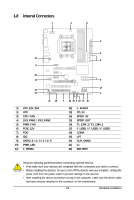
Gigabyte GA-M750SLI-DS4 Manual - Page 25
/5 CPU_FAN / SYS_FAN1 / SYS_FAN2 / PWR_FAN Fan Headers, PCIE_12V Power Connector - voltage
 |
View all Gigabyte GA-M750SLI-DS4 manuals
Add to My Manuals
Save this manual to your list of manuals |
Page 25 highlights
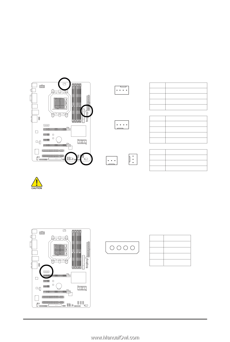
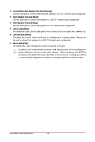
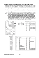
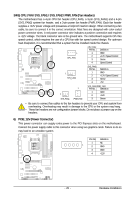
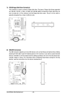
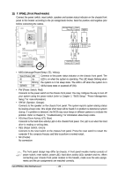
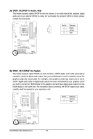
3/4/5) CPU_FAN / SYS_FAN1 / SYS_FAN2 / PWR_FAN (Fan Headers) The motherboard has a 4-pin CPU fan header (CPU_FAN), a 3-pin (SYS_FAN1) and a 4-pin (SYS_FAN2) system fan header, and a 3-pin power fan header (PWR_FAN). Each fan header supplies a +12V power voltage and possesses a foolproof insertion design. When connecting a fan cable, be sure to connect it in the correct orientation. Most fans are designed with color-coded power connector wires. A red power connector wire indicates a positive connection and requires a +12V voltage. The black connector wire is the ground wire. The motherboard supports CPU fan speed control, which requires the use of a CPU fan with fan speed control design. For optimum heat dissipation, it is recommended that a system fan be installed inside the chassis. 1 CPU_FAN CPU_FAN: Pin No. 1 2 3 4 Definition GND +12V / Speed Control Sense Speed Control 1 SYS_FAN2 SYS_FAN2: Pin No. 1 2 3 4 Definition GND +12V / Speed Control Sense +5V 1 1 SYS_FAN1 PWR_FAN SYS_FAN1/PWR_FAN: Pin No. Definition 1 GND 2 +12V 3 Sense • Be sure to connect fan cables to the fan headers to prevent your CPU and system from overheating. Overheating may result in damage to the CPU or the system may hang. • These fan headers are not configuration jumper blocks. Do not place a jumper cap on the headers. 6) PCIE_12V (Power Connector) This power connector can supply extra power to the PCI Express slots on the motherboard. Connect the power supply cable to this connector when using two graphics cards. Failure to do so may lead to an unstable system. PIin No. Definition 1 NC 1 2 GND 3 GND 4 +12V - 25 - Hardware Installation
-
 1
1 -
2
-
3
-
4
-
5
-
6
-
7
-
8
-
9
-
10
-
11
-
12
-
13
-
14
-
15
-
16
-
17
-
18
-
19
-
 20
20 -
 21
21 -
 22
22 -
 23
23 -
 24
24 -
 25
25 -
 26
26 -
 27
27 -
 28
28 -
 29
29 -
 30
30 -
31
-
32
-
33
-
34
-
35
-
36
-
37
-
38
-
39
-
40
-
41
-
42
-
43
-
44
-
45
-
46
-
47
-
48
-
49
-
50
-
51
-
52
-
53
-
54
-
55
-
56
-
57
-
58
-
59
-
60
-
61
-
62
-
63
-
64
-
65
-
66
-
67
-
68
-
69
-
70
-
71
-
72
-
73
-
74
-
75
-
76
-
77
-
78
-
79
-
80
-
81
-
82
-
83
-
84
-
85
-
86
-
87
-
88
-
89
-
90
-
91
-
92
-
93
-
94
-
95
-
96
-
97
-
98
-
99
-
100
-
101
-
102
-
103
-
104
 |
 |