Harman Kardon AVR 140 Owners Manual - Page 7
Rear-panel Connections - bridge
 |
View all Harman Kardon AVR 140 manuals
Add to My Manuals
Save this manual to your list of manuals |
Page 7 highlights
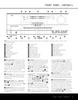
¡ ™ £ ¢ REAR-PANEL CONNECTIONS 31 j h f db · ‡ fi‹ 32 ki g e ca° fl › 140 The Bridge (100W, 1A MAX) (50W, 0.5A MAX) ∞ ¶ ª ⁄ § • ,¤ NOTE: To make it easier to follow the instructions that refer to this illustration, a larger copy may be downloaded from the Product Support section for this product at www.harmankardon.com. ¡ FM Antenna Jack ™ CD Audio Inputs £ Tape Outputs ¢ Tape Inputs ∞ Subwoofer Output § Front Speaker Outputs ¶ Surround Back Speaker Outputs • Surround Speaker Outputs ª Center Speaker Outputs , Component Video Monitor Outputs ⁄ Component Video 1 Inputs ¤ Component Video 2 Inputs ‹ AC Power Cord › Switched AC Accessory Outlet fi Unswitched AC Accessory Outlet fl Optical Digital Audio Output ‡ Coaxial Digital Audio Output ° S-Video Monitor Output · Coaxial Digital Audio Inputs a DVD S-Video Input b TheBridgeTM DMP Connector c Video 1 S-Video Input d Optical Digital Audio Inputs e Video 1 S-Video Output f Video 2 S-Video Input g 6/8-Channel Direct Inputs h Video Monitor Output i DVD Audio/Video Inputs j Video 1 Audio/Video Inputs k Video 1 Audio/Video Outputs U Video 2 Audio/Video Inputs V AM Antenna Terminals NOTE: To assist in making the correct connections for multichannel input, output and speaker connec- tions, all connection jacks and terminals are color- coded in conformance with the CEA standards as follows: Front Left: White Front Right: Center: Surround Left: Surround Right: Surround Back Left: Surround Back Right: Red Green Blue Gray Brown Tan Subwoofer: Purple Coaxial Digital Audio: Orange Composite Video: Yellow Component Video "Y": Green Component Video "Pr": Red Component Video "Pb": Blue ¡ FM Antenna Jack: Connect the supplied indoor (or an optional external) FM antenna to this terminal. ™ CD Audio Inputs: Connect these jacks to the analog audio outputs of a compact disc player or CD changer. £ Tape Outputs: Connect these jacks to the RECORD/INPUT jacks of an audio recorder. ¢ Tape Inputs: Connect these jacks to the PLAY/OUT jacks of an audio recorder. ∞ Subwoofer Output: Connect this jack to the linelevel input of a powered subwoofer. If an external subwoofer amplifier is used, connect this jack to the subwoofer amplifier input. § Front Speaker Outputs: Connect these outputs to the matching + or - terminals on your left and right speakers. When making speaker connections always make certain to maintain correct polarity by connecting the color-coded (white for front left and red for front right) (+) terminals on the AVR 140 to the red (+) terminals on the speakers and the black (-) terminals on the AVR 140 to the black (-) terminals on the speakers. See page 12 for more information on speaker polarity. ¶ Surround Back Speaker Outputs: These speaker terminals are normally used to power the surround back speaker in a 6.1-channel system. Connect these outputs to the matching + and - terminals on your surround back channel speaker. In conformance with the CEA color-code specification, the brown ter- REAR-PANEL CONNECTIONS 7
-
 1
1 -
 2
2 -
 3
3 -
 4
4 -
 5
5 -
 6
6 -
 7
7 -
 8
8 -
 9
9 -
 10
10 -
 11
11 -
 12
12 -
13
-
14
-
15
-
16
-
17
-
18
-
19
-
20
-
21
-
22
-
23
-
24
-
25
-
26
-
27
-
28
-
29
-
30
-
31
-
32
-
33
-
34
-
35
-
36
-
37
-
38
-
39
-
40
-
41
-
42
-
43
-
44
-
45
-
46
-
47
-
48
-
49
-
50
-
51
-
52
-
53
-
54
-
55
-
56
-
57
-
58
-
59
-
60
 |
 |
