HP 3PAR StoreServ 7400 2-node HP 3PAR StoreServ 7000 Storage Service Guide
HP 3PAR StoreServ 7400 2-node Manual
 |
View all HP 3PAR StoreServ 7400 2-node manuals
Add to My Manuals
Save this manual to your list of manuals |
HP 3PAR StoreServ 7400 2-node manual content summary:
- HP 3PAR StoreServ 7400 2-node | HP 3PAR StoreServ 7000 Storage Service Guide - Page 1
HP 3PAR StoreServ 7000 Storage Service Guide Abstract This guide provides information about HP 3PAR StoreServ 7000 Storage system for authorized technicians installing/uninstalling, servicing, and upgrading the system and associated hardware components. HP Part Number: QR482-96341 Published: April - HP 3PAR StoreServ 7400 2-node | HP 3PAR StoreServ 7000 Storage Service Guide - Page 2
to change without notice. The only warranties for HP products and services are set forth in the express warranty statements accompanying such products and services. Nothing herein should be construed as constituting an additional warranty. HP shall not be liable for technical or editorial errors - HP 3PAR StoreServ 7400 2-node | HP 3PAR StoreServ 7000 Storage Service Guide - Page 3
Contents 1 Servicing the Storage System 5 Service Processor Onsite Customer Care 5 Accessing the HP 3PAR Management Console 5 CSR...5 CSR Types...6 Accessing Replacement Videos 6 Parts-only Warranty Service 6 Identifying a Replaceable Part...6 Identifying Swappable Components 7 Getting - HP 3PAR StoreServ 7400 2-node | HP 3PAR StoreServ 7000 Storage Service Guide - Page 4
Pin-outs 45 Manually Initializing the Storage System Software 45 Manually Setting up the Storage System 45 Installing HP 3PAR OS Files ...48 Adding a Storage System to the Service Processor 49 Exporting Test LUNs...51 Defining Hosts...51 Creating and Exporting Test Volumes 52 B Node Rescue 53 - HP 3PAR StoreServ 7400 2-node | HP 3PAR StoreServ 7000 Storage Service Guide - Page 5
and replacement procedures on the HP 3PAR StoreServ 7000 Storage systems. CAUTION: Before servicing any component in the storage system, prepare an Electrostatic Discharge-safe (ESD) work surface by placing an antistatic mat on the floor or table near the storage system. Attach the ground lead of - HP 3PAR StoreServ 7400 2-node | HP 3PAR StoreServ 7000 Storage Service Guide - Page 6
for self repair. For assistance, contact an HP-authorized service provider to replace the part. These parts include the drive and node enclosures, the I/O modules, PCMs, and internal components of the controller node in the HP 3PAR StoreServ 7000 systems. The following are CSR components: • Disk - HP 3PAR StoreServ 7400 2-node | HP 3PAR StoreServ 7000 Storage Service Guide - Page 7
HP Spare part number Identifying Swappable Components Colored touch points on a storage system component (such as a lever or latch) identify whether the system replacement can be made. Drives must be replaced within 10 minutes, nodes 30 minutes and all other parts within 6 minutes. • Before replacing - HP 3PAR StoreServ 7400 2-node | HP 3PAR StoreServ 7000 Storage Service Guide - Page 8
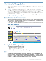
HP Storage Systems Guided Troubleshooting web site, follow the link for your product. 3. At the bottom of the HP 3PAR product page, click the link for HP 3PAR in the alert. The next page shows the message type based on the message code selected and provides a link to the Servicing the Storage System - HP 3PAR StoreServ 7400 2-node | HP 3PAR StoreServ 7000 Storage Service Guide - Page 9
Disk Drive Identification 1. Under the Systems tree in the left panel of HP 3PAR Management Console, select the storage system to be serviced. The Summary tab should be displayed indicating the failed drive (see Figure 4 (page 9)). Figure 4 Summary Tab NOTE: The Physical Disks may indicate Degraded - HP 3PAR StoreServ 7400 2-node | HP 3PAR StoreServ 7000 Storage Service Guide - Page 10
10)). Figure 7 Cage Link for Failed Drive 3. Select the Locate icon in the top toolbar of the Management Console. Figure 8 Tool Bar Locate Icon 10 Servicing the Storage System - HP 3PAR StoreServ 7400 2-node | HP 3PAR StoreServ 7000 Storage Service Guide - Page 11
Locate Cage dialog box, enter an appropriate time to allow service personnel to view the LED status of the Drive Enclosure disk drive, see "Installing a Disk Drive" (page 12). Figure 10 7200 and 7400 Two Node System (HP M6710 Drive Enclosure) Removing a 3.5 inch Disk To remove a 3.5 inch disk drive: - HP 3PAR StoreServ 7400 2-node | HP 3PAR StoreServ 7000 Storage Service Guide - Page 12
the drives based on drive type, speed, and capacity. For more information, see "Guidelines for Installing Disk Drives and Disk Enclosures" in the HP 3PAR StoreServ 7000 Storage Installation Guide. Installing a enclosure until it engages; push firmly until it clicks. 12 Servicing the Storage System - HP 3PAR StoreServ 7400 2-node | HP 3PAR StoreServ 7000 Storage Service Guide - Page 13
Figure 12 7200 and 7400 Two Node System (HP M6710 Drive Enclosure) Installing a 3.5 inch disk drive (LFF) 1. Press the handle latch drive has been successfully replaced. 2. Redisplay the physical disks to monitor. Open the system in the Systems tab and select Physical Disks. Disk Drive Repair 13 - HP 3PAR StoreServ 7400 2-node | HP 3PAR StoreServ 7000 Storage Service Guide - Page 14
take several hours. When the process is complete, the failed drive is dismissed and dropped from the display. Disk Drive Numbering Figure 14 7200 and 7400 2-Node - displayed as DCN1 in software output 14 Servicing the Storage System - HP 3PAR StoreServ 7400 2-node | HP 3PAR StoreServ 7000 Storage Service Guide - Page 15
Figure 15 7400 4-Node - displayed as DCN1 in software output Figure 16 M6710: 2U24 - displayed as DCS2 in software output Figure 17 M6720: 4U24 - displayed as DCS1 in software output Disk Drive Repair 15 - HP 3PAR StoreServ 7400 2-node | HP 3PAR StoreServ 7000 Storage Service Guide - Page 16
3PAR Management Console or HP 3PAR CLI to identify and halt the failed node. NOTE: If the failed node is already halted, it is not necessary to shutdown (halt) the node because it is not part of the cluster. The following figure illustrates the 7200 controller node. 16 Servicing the Storage System - HP 3PAR StoreServ 7400 2-node | HP 3PAR StoreServ 7000 Storage Service Guide - Page 17
following figure illustrates the 7400 controller node. Figure 19 7400 Node Identification Node Identification and Preparation NOTE: If the failed node is already halted, it is not necessary to shutdown the node because it is not part of the cluster. Controller Node (Node) Replacement Procedure 17 - HP 3PAR StoreServ 7400 2-node | HP 3PAR StoreServ 7000 Storage Service Guide - Page 18
the storage system to be serviced. In this case, there is only one controller node present, which indicates that the other node is not part of the cluster. If the node UID LED is blue proceed to step 4 to locate the system. If the node UID LED is not blue, escalate to the next level of support. NOTE - HP 3PAR StoreServ 7400 2-node | HP 3PAR StoreServ 7000 Storage Service Guide - Page 19
Replacement Instructions and Video to go to the HP Services Media Library (SML). NOTE: You may already have this window open. iv. Navigate to your Storage System type: • Product Type - Storage • Product Family - 3PAR Storage Systems • Product Series - HP 3PAR StoreServ 7000 Storage Systems v. Launch - HP 3PAR StoreServ 7400 2-node | HP 3PAR StoreServ 7000 Storage Service Guide - Page 20
to view the LED status of the System. NOTE: If necessary use the Stop Locate icon to halt LED flashing. Figure 21 Setting Permission for Time This flashes the LEDs on all of the drives and all nodes in this System except the failed node, which has a solid blue LED. 20 Servicing the Storage System - HP 3PAR StoreServ 7400 2-node | HP 3PAR StoreServ 7000 Storage Service Guide - Page 21
3. Remove cables from the failed node. 4. Pull the node rod to remove the node from the enclosure. 5. When the node is halfway out of the enclosure, use both hands to slide the node out completely. 6. Set the node on the ESD safe mat next to the replacement node for servicing. 7. Push in the failed - HP 3PAR StoreServ 7400 2-node | HP 3PAR StoreServ 7000 Storage Service Guide - Page 22
that the node LED is blinking green in synchronization with other nodes, indicating that the node has joined the cluster. 9. Follow the return instructions provided with the replaced node may indicate Green and could take up to 3 minutes to change to Green Blinking. 22 Servicing the Storage System - HP 3PAR StoreServ 7400 2-node | HP 3PAR StoreServ 7000 Storage Service Guide - Page 23
: Customers should replace a controller node only on StoreServ 7200 Storage; other internal components should be serviced by ASPs. CAUTION: Alloy gray-colored latches on components like the node means that the component is warm-swappable. HP recommends that the node be shutdown (with the power - HP 3PAR StoreServ 7400 2-node | HP 3PAR StoreServ 7000 Storage Service Guide - Page 24
: The Node Fault LED may be amber, depending on the nature of the node failure. Figure 23 Verify Node LED Status NOTE: Nodes 1 and 3 are rotated with respect to nodes 0 and 2. 2. Ensure that all cables on the failed node are marked to facilitate reconnecting later. 24 Servicing the Storage System - HP 3PAR StoreServ 7400 2-node | HP 3PAR StoreServ 7000 Storage Service Guide - Page 25
joining the cluster. This may take up to 10 minutes. 8. Verify that the node LED is blinking green in synchronization with other nodes, indicating that the node has joined the cluster. 9. Follow the return instructions provided with the new component. NOTE: If a PCIe adapter is installed in the - HP 3PAR StoreServ 7400 2-node | HP 3PAR StoreServ 7000 Storage Service Guide - Page 26
HBA/CNA and there are two to six SFPs per node. Before you begin, use either SPMAINT or the HP 3PAR Management Console to identify the failed SFP. SFP Identification 1. Under the Systems tree in the left panel, select the storage system to be serviced. 2. On the Summary tab, click the Port link to - HP 3PAR StoreServ 7400 2-node | HP 3PAR StoreServ 7000 Storage Service Guide - Page 27
be listed as Ready, the Mode as Target and the Connected Device Type as Host. To perform maintenance using CLI, access SPMAINT: 1. In the 3PAR Service Processor Menu, select option 7 Interactive CLI for an InServ. 2. Issue the following commands: • showport to view the port State: s750 cli%showport - HP 3PAR StoreServ 7400 2-node | HP 3PAR StoreServ 7000 Storage Service Guide - Page 28
-Manufacturer- MaxSpeed(Gbps) TXDisable TXFault RXLoss DDM 0:1:1 OK HP-F 8.5 No No No Yes 0:1:2 OK HP-F 8.5 No No No Yes 0:2:1 OK AVAGO 10.3 No 50002AC1010185A6 disk SAS - - - 1:0:2 initiator ready 50002ACFF70185A6 50002AC1020185A6 disk SAS - 28 Servicing the Storage System - HP 3PAR StoreServ 7400 2-node | HP 3PAR StoreServ 7000 Storage Service Guide - Page 29
No Yes 1:2:1 OK HP-F 8.5 No No Yes Yes 1:2:2 OK HP-F 8.5 No No Yes Yes 1:2:3 OK HP-F 8.5 No No Yes Yes 1:2:4 OK HP-F 8.5 No No Yes Yes Open the HP 3PAR Management Console 1. Under the Systems tree in the left panel, select the storage system to be serviced to connect. 2. On - HP 3PAR StoreServ 7400 2-node | HP 3PAR StoreServ 7000 Storage Service Guide - Page 30
See "Replacing an SFP" (page 30). 6. In the HP 3PAR Management Console, verify that the SFP is successfully replaced. The failed SFP into the packaging for return to HP. 5. Reconnect the cable to the SFP module and verify that the link status LED is solid green. 30 Servicing the Storage System - HP 3PAR StoreServ 7400 2-node | HP 3PAR StoreServ 7000 Storage Service Guide - Page 31
2 Understanding LED Indicator Status Storage system components have LEDs to indicate status of the hardware and whether it is functioning properly. These indicators help diagnose basic hardware problems. You can quickly identify hardware problems by examining the LEDs on all components using the - HP 3PAR StoreServ 7400 2-node | HP 3PAR StoreServ 7000 Storage Service Guide - Page 32
. The I/O module Fault LEDs at the rear of the enclosure also blink. Normal operation Activity Storage System Component LEDs The storage system includes the following components in the enclosure at the rear of the system. Power Cooling Module LEDs The PCM has four or six LEDs, depending on PCM, and - HP 3PAR StoreServ 7400 2-node | HP 3PAR StoreServ 7000 Storage Service Guide - Page 33
Hard fault (not recoverable) Soft fault (recoverable) Present and charged Charging or disarmed Drive PCM LEDs The following figure shows the drive enclosure PCM LEDs. Storage System Component LEDs 33 - HP 3PAR StoreServ 7400 2-node | HP 3PAR StoreServ 7000 Storage Service Guide - Page 34
Fail Amber On Flashing No AC power or fault or out of tolerance Firmware download I/O Modules LEDs I/O modules are located on the back of the system. I/O modules have two mini-SAS universal ports, which can be connected to HBAs or other ports and each port includes External Port Activity LEDs - HP 3PAR StoreServ 7400 2-node | HP 3PAR StoreServ 7000 Storage Service Guide - Page 35
for Data Ports 0 through 3 Appearance Green State On Off Flashing Meaning Ready, no activity Not ready or no power Activity Controller Node and Internal Component LEDs Controller node LEDs are shown in Table 6 (page 35). NOTE: Issue the locatenode command to flash the hotplug LED blue. Table - HP 3PAR StoreServ 7400 2-node | HP 3PAR StoreServ 7000 Storage Service Guide - Page 36
Ethernet LEDs The controller node has two built-in Ethernet ports and each includes two LEDs (see No link established or 10 Mbit Link No link activity No link established Link activity Node FC and CNA Port LEDs The controller node has two FC ports; each includes two LEDs. The arrow head-shaped LEDs - HP 3PAR StoreServ 7400 2-node | HP 3PAR StoreServ 7000 Storage Service Guide - Page 37
Slot:Port FC-1 1:1 FC-2 1:2 Table 12 FC Adapter Ports 1 2 3 4 Table 13 CNA Ports 1 2 Slot:Port 2:1 2:2 2:3 2:4 Slot:Port 2:1 2:2 SAS Port LEDs The controller node has two SAS ports and each includes four LEDs, numbered 0-3: Figure 34 SAS port LEDs Table 14 SAS port LEDs Appearance Green - HP 3PAR StoreServ 7400 2-node | HP 3PAR StoreServ 7000 Storage Service Guide - Page 38
port LEDs should always be off. 7400 Fault Status Amber On Failed to establish link connection Off No error currently on link Flashing 1. Interconnect cabling error 2. Controller node in wrong slot 3. Serial number mismatch between controller nodes Green On Off Link established Link not - HP 3PAR StoreServ 7400 2-node | HP 3PAR StoreServ 7000 Storage Service Guide - Page 39
or Service Agreement ID (if applicable) • Product serial numbers • Error messages • Operating system type and revision level • Detailed questions Specify the type of support you are requesting: HP 3PAR storage system HP 3PAR StoreServ 7200 and 7400 Storage systems HP 3PAR StoreServ 10000 Storage - HP 3PAR StoreServ 7400 2-node | HP 3PAR StoreServ 7000 Storage Service Guide - Page 40
and manage HP 3PAR Remote Copy HP 3PAR Remote Copy Software User's Guide Updating HP 3PAR operating systems HP 3PAR Upgrade Pre-Planning Guide Identifying storage system components, troubleshooting information, and detailed alert information HP 3PAR F-Class, T-Class, and StoreServ 10000 Storage - HP 3PAR StoreServ 7400 2-node | HP 3PAR StoreServ 7000 Storage Service Guide - Page 41
upgrading 7200 and 7400 storage systems Troubleshooting 7200 and 7400 storage systems Maintaining the Service Processor HP 3PAR StoreServ 7000 Storage Service Guide HP 3PAR StoreServ 7000 Storage Troubleshooting Guide HP 3PAR Service Processor Software User Guide HP 3PAR Service Processor Onsite - HP 3PAR StoreServ 7400 2-node | HP 3PAR StoreServ 7000 Storage Service Guide - Page 42
in order to achieve a functional and supported implementation based on testing at HP. HP 3PAR branding information • The server previously referred to as the "InServ" is now referred to as the "HP 3PAR StoreServ Storage system." • The operating system previously referred to as the "InForm OS - HP 3PAR StoreServ 7400 2-node | HP 3PAR StoreServ 7000 Storage Service Guide - Page 43
4 Documentation feedback HP is committed to providing documentation that meets your needs. To help us improve the documentation, send any errors, suggestions, or comments to Documentation Feedback ([email protected]). Include the document title and part number, version number, or the URL when - HP 3PAR StoreServ 7400 2-node | HP 3PAR StoreServ 7000 Storage Service Guide - Page 44
or SPOCC to perform maintenance procedures. For more information on servicing the storage system, see the HP 3PAR StoreServ 7000 Storage Service Guide. Connecting the Laptop to the Controller Node Connect the RJ45 cable to the controller node MFG ports (known as the public interface) to the laptop - HP 3PAR StoreServ 7400 2-node | HP 3PAR StoreServ 7000 Storage Service Guide - Page 45
Laptop to the SP" in the HP 3PAR StoreServ 7000 Storage Installation Guide. Manually Setting up the Storage System The Out-of-the-Box (OOTB) script guides you through setting up and configuring the storage system software: 1. Connect the PC to the controller node 0 through a serial cable and log in - HP 3PAR StoreServ 7400 2-node | HP 3PAR StoreServ 7000 Storage Service Guide - Page 46
nodes in the system, then type c and press Enter. If the system is not ready for the system setup script, an error message appears. After following any instructions and correcting any problems press Enter. 7. Name the storage system using up to 31 alphanumeric characters. Type yes and press - HP 3PAR StoreServ 7400 2-node | HP 3PAR StoreServ 7000 Storage Service Guide - Page 47
==> c 9. Verify the number of drives in the storage system. Type c and press Enter to continue. 10. If HP recommends that at least four physical disks worth of chunklets be designated as spares to support , but is not recommended as spares must be manually added when new disks are added. Enter "Ma - HP 3PAR StoreServ 7400 2-node | HP 3PAR StoreServ 7000 Storage Service Guide - Page 48
-Of-The-Box Experience... Installing HP 3PAR OS Files After completing the Service Processor Setup wizard process, HP 3PAR OS files must first be installed onto the SP in order to communicate and add a storage system. To install the OS files: 1. Insert the HP 3PAR OS Release Distribution CD into the - HP 3PAR StoreServ 7400 2-node | HP 3PAR StoreServ 7000 Storage Service Guide - Page 49
Base Image Version: 3.1-8 SP Version: 2.5.1.GA-15 SP Patches: InFormOS release (3.1.2): 3.1.2.226 More detail is available in the latest SPLOR or spconfig data. Press to continue Continue to "Adding a Storage System to the Service Processor" (page 49). Adding a Storage System - HP 3PAR StoreServ 7400 2-node | HP 3PAR StoreServ 7000 Storage Service Guide - Page 50
To add the storage system to the SP: 1. Connect the maintenance PC to the SP. 2. In the SPMaint, type 3 and press Enter to select InServ Configuration Management. SPXXXXX 1 SP Main 3PAR Service Processor Menu Transfer media: ethernet Transfer status: No transfer yet Enter Control-C at any time - HP 3PAR StoreServ 7400 2-node | HP 3PAR StoreServ 7000 Storage Service Guide - Page 51
that the storage system is ready for use. NOTE: Before you can export test LUNs, you must determine the host Fibre Channel connection types and set the appropriate port personas for all target ports, or ports that connect to host computers. See the HP 3PAR Implementation Guides where appropriate - HP 3PAR StoreServ 7400 2-node | HP 3PAR StoreServ 7000 Storage Service Guide - Page 52
connected WWN, verify host configuration information for the storage system as follows: 192.168.46.249 cli% showhost 4. Use the controlport command to set each target port as follows: 192.168.46.249 cli% controlport config [-ct loop | point] where is the name - HP 3PAR StoreServ 7400 2-node | HP 3PAR StoreServ 7000 Storage Service Guide - Page 53
B Node Rescue Service Processor (Physical) Node Rescue The SP node rescue should be used only in cases when the storage system includes a physical SP and no nodes remain in the cluster or when all nodes are down. NOTE: For SP node rescue, you can specify whether to use the public Ethernet port (MGMT - HP 3PAR StoreServ 7400 2-node | HP 3PAR StoreServ 7000 Storage Service Guide - Page 54
to the main menu • 7 Interactive CLI for an InServ, then select the desired system 7. Issue the following commands: • shownode to verify that all nodes have joined the cluster. cli% shownode Control Data Cache Node Name -State- Master InCluster --LED-- Mem(MB) Mem(MB) Available(%) 2 1201553-2 OK - HP 3PAR StoreServ 7400 2-node | HP 3PAR StoreServ 7000 Storage Service Guide - Page 55
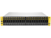
The following shows each component of the storage system for all replaceable hardware parts including the part number, full description, quantity, and CSR type. Drive Enclosure Components Figure 37 HP M6710 Drive Enclosure (2U24) Figure 38 HP M6720 Drive Enclosure (4U24) Drive Enclosure Components - HP 3PAR StoreServ 7400 2-node | HP 3PAR StoreServ 7000 Storage Service Guide - Page 56
Figure 39 2.5-inch SFF disk drive Figure 40 3.5-inch LFF disk drive Table 17 Drive Chassis FRUs Material Number Description 683232-001 SPS-Enclosure Midplane 2U24 Assy 683233-001 SPS-Enclosure Midplane 4U24 Assy 683234-001 SPS-Drive Carrier SFF SSD Assy 683235-001 SPS-Drive Carrier LFF - HP 3PAR StoreServ 7400 2-node | HP 3PAR StoreServ 7000 Storage Service Guide - Page 57
-Drive HD 100GB 6G SAS 3.5in HDD 703522-001 SPS-Drive 100GB 6G SAS 3.5in HDD 703523-001 SPS-Drive 200GB 6G SAS 3.5in HDD Storage System Components Figure 41 764W Power Cooling Module without Battery CSR Type Mandatory Mandatory Mandatory Mandatory Mandatory Mandatory Mandatory - HP 3PAR StoreServ 7400 2-node | HP 3PAR StoreServ 7000 Storage Service Guide - Page 58
Figure 42 764W Power Cooling Module Battery Figure 43 580W Power Cooling Module Figure 44 I/O Module 58 Illustrated Parts Catalog - HP 3PAR StoreServ 7400 2-node | HP 3PAR StoreServ 7000 Storage Service Guide - Page 59
Table 18 Storage System Components Part Number 683239-001 683240-001 683241-001 683251-001 Description SPS-PCM 764W Assy SPS-Battery PCM 764W Assy SPS-PCM 580W Assy SPS-Module I/O SASquatch Controller Node and Internal Components Figure 45 Controller Node Qty. up to 2 up to 2 up to 2 up to 4 - HP 3PAR StoreServ 7400 2-node | HP 3PAR StoreServ 7000 Storage Service Guide - Page 60
Figure 47 4-port Fibre Channel Adapter Figure 48 2-port CNA Adapter Figure 49 FC SFP Adapter 60 Illustrated Parts Catalog - HP 3PAR StoreServ 7400 2-node | HP 3PAR StoreServ 7000 Storage Service Guide - Page 61
-001 683237-001 468508-002 Description SPS-Node Module 7200 NO HBA SPS-Node Module 7400 NO HBA SPS-Node Boot Drive (Node drive) SPS-Adapter FC 4port SPS-Adapter CNA 2port SPS-Module FC SFP Figure 50 Internal Node Components Qty. 2 4 1 per node 1 1 Up to 4 per node CSR Type Optional Not Not Not - HP 3PAR StoreServ 7400 2-node | HP 3PAR StoreServ 7000 Storage Service Guide - Page 62
and Parts Table 21 Storage System Cables Part Number 683808-001 683809-001 683810-001 683252-001 656427-001 656428-001 656429-001 656430-001 656431-001 656432-001 649991-001 649992-001 649993-001 Description Qty. SPS-Cable Node Link PCIe 7400 SPS-Cable Console Node SPS-Cable Console Drive - HP 3PAR StoreServ 7400 2-node | HP 3PAR StoreServ 7000 Storage Service Guide - Page 63
21 Storage System Cables shelf, left 683257-001 SPS-Bezel 7200, right 683258-001 SPS-Bezel 7400, left 690777-001 SPS-Bezel M6720 drive shelf, right 690778-001 SPS SFF 697273-001 SPS-Drive blank LFF Table 23 Service Processor Parts Part Number 683811-001 675040-001 647980-001 707989-001 - HP 3PAR StoreServ 7400 2-node | HP 3PAR StoreServ 7000 Storage Service Guide - Page 64
Table 23 Service Processor Parts (continued) Part Number Description Qty. 5183-5691 Ethernet Cable 50 ft. CAT5 RJ45 M/M C7542A HP Ethernet 15.2m (50 ft) CAT5e RJ45 M/M Cable CSR Type Mandatory 64 Illustrated Parts Catalog - HP 3PAR StoreServ 7400 2-node | HP 3PAR StoreServ 7000 Storage Service Guide - Page 65
showpd • Storage system hardware configuration • Number of enclosures and nodes • Physical condition of system hardware and Storage System Components from an Existing or Third Party Rack See the appropriate component removal procedures in "Servicing the Storage System" (page 5). Storage System
-
 1
1 -
 2
2 -
 3
3 -
 4
4 -
 5
5 -
 6
6 -
 7
7 -
8
-
9
-
10
-
11
-
12
-
13
-
14
-
15
-
16
-
17
-
18
-
19
-
20
-
21
-
22
-
23
-
24
-
25
-
26
-
27
-
28
-
29
-
30
-
31
-
32
-
33
-
34
-
35
-
36
-
37
-
38
-
39
-
40
-
41
-
42
-
43
-
44
-
45
-
46
-
47
-
48
-
49
-
50
-
51
-
52
-
53
-
54
-
55
-
56
-
57
-
58
-
59
-
60
-
61
-
62
-
63
-
64
-
65
 |
 |

HP 3PAR StoreServ 7000 Storage Service
Guide
Abstract
This guide provides information about HP 3PAR StoreServ 7000 Storage system for authorized technicians installing/uninstalling,
servicing, and upgrading the system and associated hardware components.
HP Part Number: QR482-96341
Published: April 2013