HP 550 HP 550 Notebook PC - Maintenance and Service Guide - Page 53
Optical drive, Remove the slotted Torx ST8M2.5×7.0 screw
 |
View all HP 550 manuals
Add to My Manuals
Save this manual to your list of manuals |
Page 53 highlights
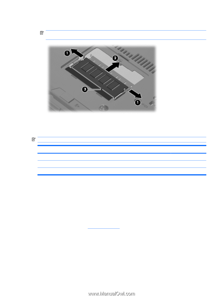
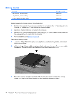
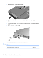
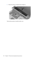
4. Remove the memory module (2) by pulling the module away from the slot at an angle. NOTE: Memory modules are designed with a notch (3) to prevent incorrect insertion into the memory module slot. Reverse this procedure to install a memory module. Optical drive NOTE: All optical drive spare part kits include an optical drive bezel. Description DVD±RW and CD-RW Super Multi Double-Layer Combo Drive with LightScribe DVD±RW and CD-RW Super Multi Double-Layer Combo Drive DVD/CD-RW Combo Drive Spare part number 500768-001 500767-001 500766-001 Before removing the optical drive, follow these steps: 1. Shut down the computer. If you are unsure whether the computer is off or in Hibernation, turn the computer on, and then shut it down through the operating system. 2. Disconnect all external devices connected to the computer. 3. Disconnect the power from the computer by first unplugging the power cord from the AC outlet and then unplugging the AC adapter from the computer. 4. Remove the battery (see Battery on page 38). Remove the optical drive: 1. Position the computer with the right side toward you. 2. Remove the slotted Torx ST8M2.5×7.0 screw (1) that secures the optical drive to the computer. 3. Insert a flat-bladed screwdriver or similar tool into the optical drive tab access (2) and press the tab to the left to release the optical drive from the computer. Component replacement procedures 45
-
 1
1 -
2
-
3
-
4
-
5
-
6
-
7
-
8
-
9
-
10
-
11
-
12
-
13
-
14
-
15
-
16
-
17
-
18
-
19
-
20
-
21
-
22
-
23
-
24
-
25
-
26
-
27
-
28
-
29
-
30
-
31
-
32
-
33
-
34
-
35
-
36
-
37
-
38
-
39
-
40
-
41
-
42
-
43
-
44
-
45
-
46
-
47
-
 48
48 -
 49
49 -
 50
50 -
 51
51 -
 52
52 -
 53
53 -
 54
54 -
 55
55 -
 56
56 -
 57
57 -
 58
58 -
59
-
60
-
61
-
62
-
63
-
64
-
65
-
66
-
67
-
68
-
69
-
70
-
71
-
72
-
73
-
74
-
75
-
76
-
77
-
78
-
79
-
80
-
81
-
82
-
83
-
84
-
85
-
86
-
87
-
88
-
89
-
90
-
91
-
92
-
93
-
94
-
95
-
96
-
97
-
98
-
99
-
100
-
101
-
102
-
103
-
104
-
105
-
106
-
107
-
108
-
109
-
110
-
111
-
112
-
113
-
114
-
115
-
116
-
117
-
118
-
119
-
120
-
121
-
122
-
123
-
124
-
125
-
126
-
127
-
128
-
129
-
130
-
131
-
132
-
133
-
134
-
135
-
136
-
137
-
138
-
139
-
140
-
141
-
142
-
143
-
144
-
145
-
146
-
147
-
148
 |
 |