HP 550 HP 550 Notebook PC - Maintenance and Service Guide - Page 81
Processor
 |
View all HP 550 manuals
Add to My Manuals
Save this manual to your list of manuals |
Page 81 highlights
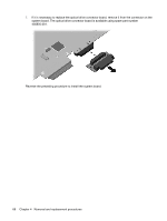
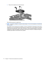
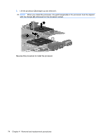
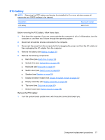
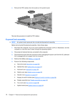
Processor NOTE: All processor spare part kits include replacement thermal material. Replacement thermal material is also available in the Thermal Material Kit, spare part number 456605-001. Description Intel Core2 Duo processors: ● T5470 1.60-GHz processor (2-MB L2 cache, 800-MHz FSB) ● T5270 1.40-GHz processor (2-MB L2 cache, 800-MHz FSB) Intel Celeron M processors: ● P540 1.86-GHz processor (1-MB L2 cache, 533-MHz FSB) ● P530 1.73-GHz processor (1-MB L2 cache, 533-MHz FSB) Intel Celeron M Dual Core processors: ● T1400 1.73-GHz (1-MB L2 cache, 533-Mhz FSB) Spare part number 500757-001 495383-001 506445-001 500756-001 506446-001 Before removing the processor, follow these steps: 1. Shut down the computer. If you are unsure whether the computer is off or in Hibernation, turn the computer on, and then shut it down through the operating system. 2. Disconnect all external devices connected to the computer. 3. Disconnect the power from the computer by first unplugging the power cord from the AC outlet and then unplugging the AC adapter from the computer. 4. Remove the battery (see Battery on page 38). 5. Remove the following components: a. Hard drive (see Hard drive on page 39) b. Optical drive (see Optical drive on page 45) c. Keyboard (see Keyboard on page 49) d. Switch cover (see Switch cover on page 46) e. Speaker (see Speaker on page 52) f. Display lid switch module (see Display lid switch module on page 53) g. Display assembly (see Display assembly on page 54) h. Top cover (see Top cover on page 59) i. System board (see System board on page 65) Remove the processor: 1. Turn the system board upside down, with the USB connectors toward you. 2. Use a flat-bladed screwdriver to turn the processor locking screw (1) one-half turn counterclockwise until you hear a click. Component replacement procedures 73
-
 1
1 -
2
-
3
-
4
-
5
-
6
-
7
-
8
-
9
-
10
-
11
-
12
-
13
-
14
-
15
-
16
-
17
-
18
-
19
-
20
-
21
-
22
-
23
-
24
-
25
-
26
-
27
-
28
-
29
-
30
-
31
-
32
-
33
-
34
-
35
-
36
-
37
-
38
-
39
-
40
-
41
-
42
-
43
-
44
-
45
-
46
-
47
-
48
-
49
-
50
-
51
-
52
-
53
-
54
-
55
-
56
-
57
-
58
-
59
-
60
-
61
-
62
-
63
-
64
-
65
-
66
-
67
-
68
-
69
-
70
-
71
-
72
-
73
-
74
-
75
-
 76
76 -
 77
77 -
 78
78 -
 79
79 -
 80
80 -
 81
81 -
 82
82 -
 83
83 -
 84
84 -
 85
85 -
 86
86 -
87
-
88
-
89
-
90
-
91
-
92
-
93
-
94
-
95
-
96
-
97
-
98
-
99
-
100
-
101
-
102
-
103
-
104
-
105
-
106
-
107
-
108
-
109
-
110
-
111
-
112
-
113
-
114
-
115
-
116
-
117
-
118
-
119
-
120
-
121
-
122
-
123
-
124
-
125
-
126
-
127
-
128
-
129
-
130
-
131
-
132
-
133
-
134
-
135
-
136
-
137
-
138
-
139
-
140
-
141
-
142
-
143
-
144
-
145
-
146
-
147
-
148
 |
 |