HP 550 HP 550 Notebook PC - Maintenance and Service Guide - Page 68
Seven slotted Torx ST8M2.5×7.0 screws, One Torx T8m2.5×4.0 screw
 |
View all HP 550 manuals
Add to My Manuals
Save this manual to your list of manuals |
Page 68 highlights
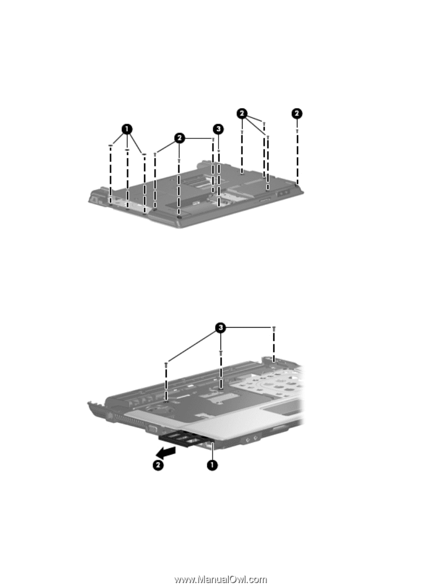
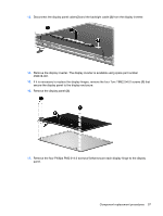
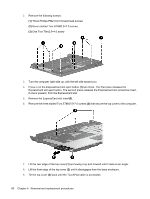
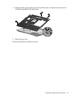
2. Remove the followng screws: (1) Three Phillips PM2.0×2.0 broad-head screws (2) Seven slotted Torx ST8M2.5×7.0 screws (3) One Torx T8m2.5×4.0 screw 3. Turn the computer right-side up, with the left side toward you. 4. Press in on the ExpressCard slot eject button (1) two times. The first press releases the ExpressCard slot eject button. The second press releases the ExpressCard slot protective insert, if one is present, from the ExpressCard slot. 5. Remove the ExpressCard slot insert(2). 6. Remove the three slotted Torx ST8M2.5×7.0 screws (3) that secure the top cover to the computer. 7. Lift the rear edge of the top cover (1) and swing it up and forward until it rests at an angle. 8. Lift the front edge of the top cover (2) until it disengages from the base enclosure. 9. Tilt the top cover (3) back until the TouchPad cable is accessible. 60 Chapter 4 Removal and replacement procedures
-
 1
1 -
2
-
3
-
4
-
5
-
6
-
7
-
8
-
9
-
10
-
11
-
12
-
13
-
14
-
15
-
16
-
17
-
18
-
19
-
20
-
21
-
22
-
23
-
24
-
25
-
26
-
27
-
28
-
29
-
30
-
31
-
32
-
33
-
34
-
35
-
36
-
37
-
38
-
39
-
40
-
41
-
42
-
43
-
44
-
45
-
46
-
47
-
48
-
49
-
50
-
51
-
52
-
53
-
54
-
55
-
56
-
57
-
58
-
59
-
60
-
61
-
62
-
 63
63 -
 64
64 -
 65
65 -
 66
66 -
 67
67 -
 68
68 -
 69
69 -
 70
70 -
 71
71 -
 72
72 -
 73
73 -
74
-
75
-
76
-
77
-
78
-
79
-
80
-
81
-
82
-
83
-
84
-
85
-
86
-
87
-
88
-
89
-
90
-
91
-
92
-
93
-
94
-
95
-
96
-
97
-
98
-
99
-
100
-
101
-
102
-
103
-
104
-
105
-
106
-
107
-
108
-
109
-
110
-
111
-
112
-
113
-
114
-
115
-
116
-
117
-
118
-
119
-
120
-
121
-
122
-
123
-
124
-
125
-
126
-
127
-
128
-
129
-
130
-
131
-
132
-
133
-
134
-
135
-
136
-
137
-
138
-
139
-
140
-
141
-
142
-
143
-
144
-
145
-
146
-
147
-
148
 |
 |