HP 550 HP 550 Notebook PC - Maintenance and Service Guide - Page 74
Remove the system board, Remove the RJ-11 jack
 |
View all HP 550 manuals
Add to My Manuals
Save this manual to your list of manuals |
Page 74 highlights
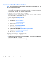
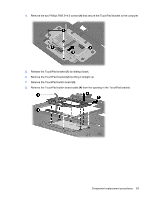
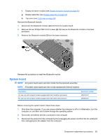
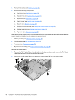
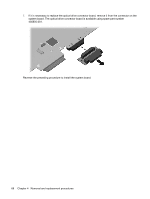
4. Remove the battery (see Battery on page 38). 5. Remove the following components: a. Hard drive (see Hard drive on page 39) b. Optical drive (see Optical drive on page 45) c. Keyboard (see Keyboard on page 49) d. Switch cover (see Switch cover on page 46) e. Speaker (see Speaker on page 52) f. Display lid switch module (see Display lid switch module on page 53) g. Display assembly (see Display assembly on page 54) h. Top cover (see Top cover on page 59) When replacing the system board, be sure that the following components are removed from the defective system board and installed on the replacement system board: ● Memory module (see Memory module on page 44) ● WLAN module (see WLAN module on page 41) ● Processor (see Processor on page 73) ● ExpressCard assembly (see ExpressCard assembly on page 78) Remove the system board: 1. Remove the RJ-11 jack (1) from the clip built into the base enclosure and remove the RJ-11 jack cable from the hook (2) built into the base enclosure. 2. Disconnect the fan cable (3) and the Bluetooth module cable (4) from the system board. 66 Chapter 4 Removal and replacement procedures
-
 1
1 -
2
-
3
-
4
-
5
-
6
-
7
-
8
-
9
-
10
-
11
-
12
-
13
-
14
-
15
-
16
-
17
-
18
-
19
-
20
-
21
-
22
-
23
-
24
-
25
-
26
-
27
-
28
-
29
-
30
-
31
-
32
-
33
-
34
-
35
-
36
-
37
-
38
-
39
-
40
-
41
-
42
-
43
-
44
-
45
-
46
-
47
-
48
-
49
-
50
-
51
-
52
-
53
-
54
-
55
-
56
-
57
-
58
-
59
-
60
-
61
-
62
-
63
-
64
-
65
-
66
-
67
-
68
-
 69
69 -
 70
70 -
 71
71 -
 72
72 -
 73
73 -
 74
74 -
 75
75 -
 76
76 -
 77
77 -
 78
78 -
 79
79 -
80
-
81
-
82
-
83
-
84
-
85
-
86
-
87
-
88
-
89
-
90
-
91
-
92
-
93
-
94
-
95
-
96
-
97
-
98
-
99
-
100
-
101
-
102
-
103
-
104
-
105
-
106
-
107
-
108
-
109
-
110
-
111
-
112
-
113
-
114
-
115
-
116
-
117
-
118
-
119
-
120
-
121
-
122
-
123
-
124
-
125
-
126
-
127
-
128
-
129
-
130
-
131
-
132
-
133
-
134
-
135
-
136
-
137
-
138
-
139
-
140
-
141
-
142
-
143
-
144
-
145
-
146
-
147
-
148
 |
 |